· Nordic · 7 min read
nRF52 as I2C Master using TWI/TWIM modules
The nRF52 series from Nordic Semiconductor offers robust support for I2C communication through its TWI (Two Wire Interface) and TWIM (TWI Master with EasyDMA) peripherals. In this post, we’ll break down the differences between TWI and TWIM, and show you how to use the nrf_drv_twi driver from the nRF5 SDK to set up the nRF52 as an I2C master. From initializing the bus to sending and receiving data, you’ll learn the essential steps needed to get your devices talking. We'll also walk through a hands-on example project to bring theory into practice — perfect for beginners and experienced developers alike.
Introduction
In our previous article, we discussed the TWIS module which is used in applications where nRF52 behaves as a slave device. nRF52 chips have two hardware blocks that facilitate I2C communication when nRF52 acts as a master device: the TWI and TWIM peripherals. In this article, we will talk about these modules. Specifically, we will cover:
- The TWI and TWIM peripherals: differences, instances, address space, pin configuration
- The nrf_drv_twi driver in nRF5 SDK to control TWI/TWIM instances
- Sample project using TWI/TWIM instances
To compile and run your code on real nRF52 hardware, it is recommended that you have a nRF52 development kit such as
Affiliate Disclosure: When you click on links in this section and make a purchase, this may result in this site earning a commission at no extra cost to you.
The TWI and TWIM peripherals
Difference between TWI and TWIM
TWI stands for Two Wire Interface and TWIM stands for Two Wire Interface Master. Both these modules are hardware dedicated blocks implementing I2C master in nRF52. The difference between these two peripherals is one module supports direct accessing RAM and the other does not. The TWIM peripheral uses EasyDMA block to read and write data buffers from RAM directly, while the TWI module does not have this capability. The TWI module is deprecated and you should use TWIM if it’s available in the nRF52 chip. The chip’s datasheet contains information about which module is available.
Instances and address space
There may be more than 1 instance of TWI/TWIM in a nRF52 chip. For instance, nRF52832 has two TWI instances (TWI0 and TWI1) and two TWIM instances (TWIM0 and TWIM1). As other peripherals, the TWI/TWIM modules are allocated 4 kB of address space. TWI0 and TWIM0 both have base address of 0x40003000 and hence they can not be used at the same time. Note that there are other peripherals having this same address (TWIS0, SPI0, SPIM0, SPIS0) and hence you need to be aware of this in your application. TWI1 and TWIM1 both have base address of 0x40004000 and share resources with TWIS1, SPI1, SPIM1, SPIS1.
Pin configuration and speed
Similar to TWIS, the SCL and SDA pins of the TWI/TWIM peripherals are mapped to physical I/O pins by software configuration which provides great flexibility. The TWI/TWIM modules support standard bus speed of 100 kHz as well as fast mode of 400 kHz.
The nrf_drv_twi driver
To control TWI/TWIM peripherals, Nordic provides nrfx_twi and nrfx_twim drivers, respectively. You can use these drivers directly in your project. Nordic also provide nrf_drv_twi driver which simplifies your job a little further by choosing whether to use nrfx_twi or nrfx_twim driver behind the scene based on the configuration in sdk_config.h. By default, if a chip only has TWI instances, it will use nrfx_twi driver. If a chip has both TWI and TWIM instances, TWIM will be preferred and nrfx_twim functions are called. In this section, we look at how to include nrf_drv_twi driver in your project and how to enable TWI/TWIM instances in your project.
Include the nrf_drv_twi driver in your project
To include the driver, you need to add several files to your source file list. The snippet below shows required files and folders that you need to add to your Makefile:

Enabling the TWI/TWIM instances in sdk_config.h
In order to use a TWI/TWIM instance, you need to enable it by defining some values in sdk_config.h. For instance, if you want to use TWIM0 instance, you need to add the following definitions to your sdk_config.h file:
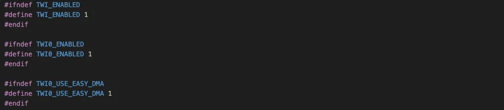
If you want to use TWI0 instance, change TWI0_USE_EASY_DMA to 0, since the difference between TWI0 and TWIM0 is directly accessing RAM using EasyDMA.
Initialisation
The first step when using the driver is to do initialisation by calling nrf_drv_twi_init(). This function will configure the TWI/TWIM parameters and prepare the module for sending and receiving data from slave device.

This function takes a few arguments:
p_instanceis a pointer to an instance structure. You can use the macroNRF_DRV_TWI_INSTANCE()with an instance index to define your instance.p_configis the address of a configuration structure which tells which pins are used as SCL and SDA, what is the I2C frequency (100 kHz, 250 kHz or 400 kHz)event_handleris a callback function that executes when a TWI event happens. An event could be:NRF_DRV_TWI_EVT_DONE: indicates a transaction is completedNRF_DRV_TWI_EVT_ADDRESS_NACK: this event is fired if NACK is received after sending the address, which means something is wrong with the slave address.NRF_DRV_TWI_EVT_DATA_NACK: an error event indicating NACK is received after sending a data byte. This could be due to the slave device is busy with other tasks and not responding.
p_contextis the context passed to event handler
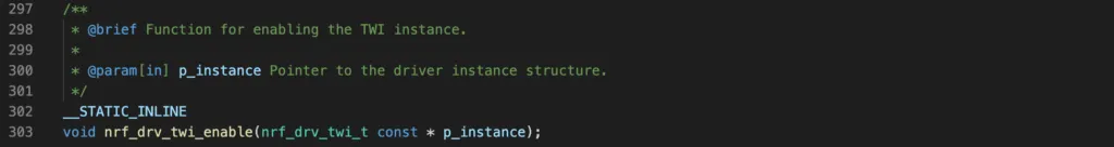
Enabling the driver
After initialised, the driver needs to be enabled by calling nrf_drv_twi_enable().
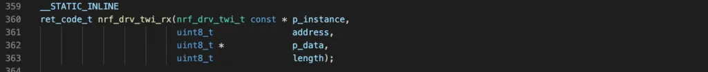
Reading data from a slave device
To read data from a slave device, the master first needs to send the address of the slave that it wants to read. After that, data is clocked out of the slave. The function to perform this task is nrf_drv_twi_rx(). You need to pass in the address of the instance that you are using, the address of the slave device, address of receive buffer and number of bytes to receive. You will need to allocate a receive buffer in advance to store the data from the slave.
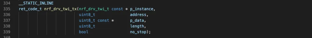
Sending data to a slave device
To send data to slave device, use the function nrf_drv_twi_tx(). This function performs necessary steps for transferring data from the TWI/TWIM instance to the slave device such as clocking out the slave address and then data from a transmit buffer.
TWI/TWIM Sample Project
In this section, we implement a simple project to read data from an I2C slave device and print it to console using NRF_LOG module.
- We will be using a PCA10040 board which has nRF52832 and use TWIM0 instance in our project
- The slave device is another PCA10040 board running nRF52 TWIS code
- The slave address is 0x11, SCL is pin 27 and SDA is pin 26.
- The TWIM0 will receive 5 bytes of data from the slave and log it on RTT console.
Code
Follow the following steps to implement the project:
- Start with a template project with NRF_LOG enabled here and download the project to your computer. It is recommended that you learn about logging using NRF_LOG module in advance and understand how it works.
- Modify Makefile to point to your correct installation folder of nRF5 SDK 17.1
- Enabling the TWIM0 instance in sdk_config.h as described in previous section.
- Add the following code to your
main.c.
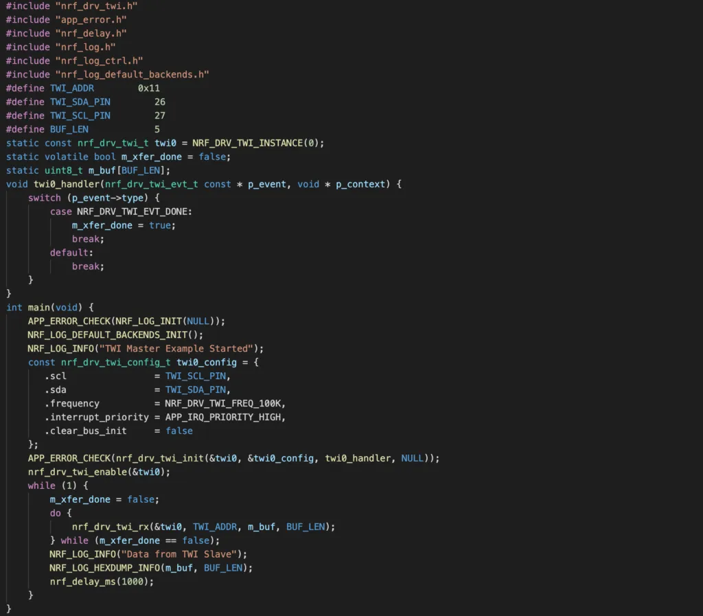
Final project code look like this.
Testing the program
To test the program, compile and flash the project using make flash. You will need two PCA10040 boards.
- Board 1: master device, run above code
- Board 2: slave device, run TWIS code
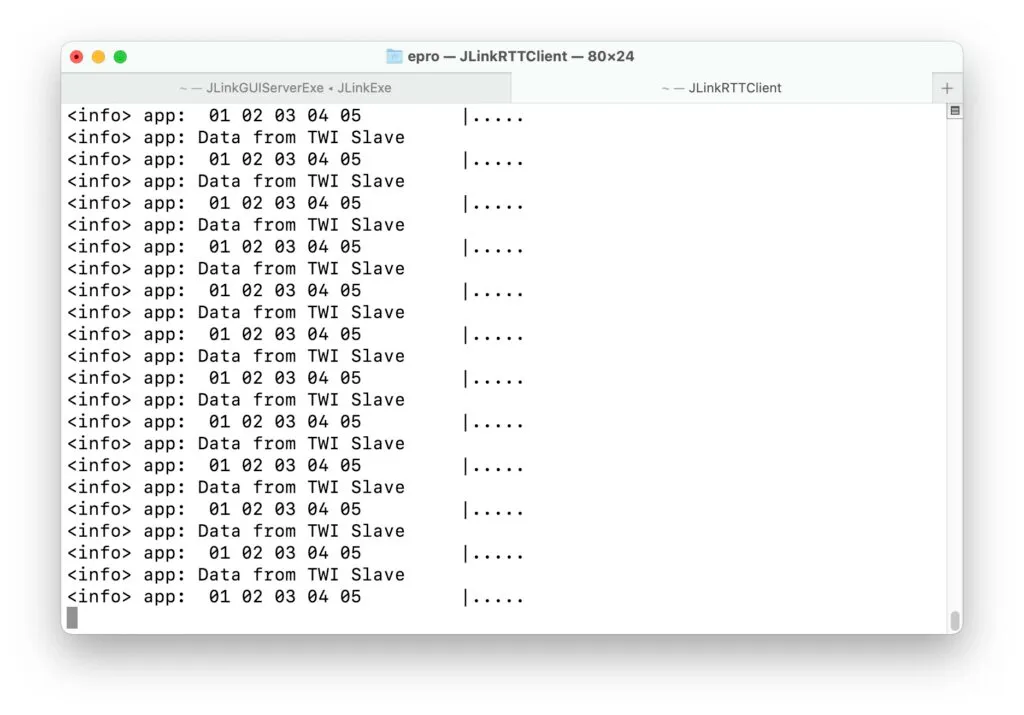
Connect pin 26 of board 1 to pin 26 of board 2, pin 27 of board 1 to pin 27 of board 2. If you see the below output, then your program is running properly. If you don’t see the output, there are a few suggestions which you might want to check. Firstly, check if the NRF_LOG module is working by printing out some dummy text. Sometimes a loose connection might be the issue why you don’t see the output. Secondly, check if the pins are wired properly. You can print out the error codes of the function nrf_drv_twi_rx() to see if it is an address error or a data error and go from there.
Wrapping Up
There are many types of sensors that implement I2C communication. If you are working with nRF52 long enough, you might eventually need to learn how to use TWI/TWIM peripherals to send and receive data from them. This guide provides a starting point so that you can dig further to Nordic documentation to work with TWI/TWIM in your application. Thanks for reading.