· Nordic · 8 min read
Understanding nRF52 PPI module and nrfx_ppi driver
The nRF52 series from Nordic Semiconductor includes the powerful Programmable Peripheral Interconnect (PPI) module, designed to enable efficient communication between peripherals without involving the CPU. This article dives deep into the PPI module’s capabilities, explaining how it can streamline tasks by triggering actions between different peripherals, such as timers, GPIOs, and ADCs. We’ll explore how to leverage the nrfx_ppi driver from the nrfx HAL to set up and control these interactions, reducing system power consumption and improving performance. With a hands-on example, you'll learn to configure the PPI for tasks like sensor data collection or motor control, all while keeping the CPU free for other critical tasks.
Introduction
In this article, you will learn about the PPI module in Nordic nRF52 and how to use nrfx_ppi driver to interact with it. The topic we cover include:
- What is PPI and why it might be useful for your project
- PPI terminologies: tasks, events, channels
- How to include and enable nrfx_ppi driver in your project
- What are common PPI APIs in nrfx_ppi driver
- A sample project that use PPI
To compile and run your code on real nRF52 hardware, it is recommended that you have a nRF52 development kit such as
Affiliate Disclosure: When you click on links in this section and make a purchase, this may result in this site earning a commission at no extra cost to you.
The nRF52 PPI peripheral
PPI stands for P rogrammable P eripheral I nterconnect. As the name suggests, PPI module allows two peripherals to communicate with each other without CPU intervention as illustrated below
Peripheral 1 ---> PPI module ---> Peripheral 2You can imagine PPI module as configurable wires that connect two peripherals. Configurable means you can choose which peripheral to connect at one end, and which peripheral to connect at the other end. Each PPI module contains 32 channels (32 “wires”) that you can use.
You can use PPI in applications where if peripheral 1 finishes some jobs and you expect peripheral 2 to be automatically notified and triggers an action. For example, peripheral 1 might be a TIMER peripheral which generates an event every 500 ms. Peripheral 2 might be a GPIOTE module which controls a GPIO pin connected to an LED. Whenever TIMER expires, the GPIO pin is toggled so that the LED blinks. You can connect TIMER’s event to one end of a PPI channel, and GPIOTE’s task to the other end of the same PPI channel. That configuration will allow the LED to blink every 500 ms with no CPU involvement.
PPI Channels
There are 32 PPI channels that are available to use. Of those, 20 channels (from 0 to 19) are configurable and 12 channels (from 20 to 31) are fixed. You can choose which peripherals to connect to configurable PPI channels. However, you can only enable or disable a fixed PPI channel, because its connections are fixed.
PPI Event End Point (EEP)
Each PPI channel has one Event End Point (EEP) which you can connect a peripheral’s event to. EEP is a register that contains the address of the peripheral’s event register.
PPI Task End Point (TEP) and Fork Task End Point (Fork TEP)
Each PPI channel has two task end points (TEP and Fork TEP). This will allow en event to trigger two tasks simultaneously.
The nrfx_ppi driver
To control PPI, you use the driver nrfx_ppi in nRF5 SDK. In this section, you will learn how to include the nrfx_driver in your project and enable PPI module in your project’s configuration.
Include the nrfx_ppi driver in your project
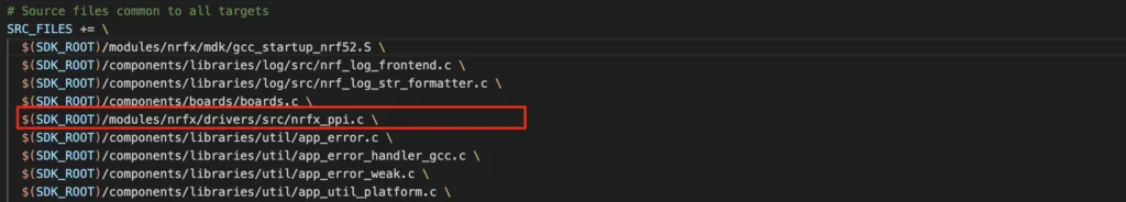
The nrfx_ppi source code is defined in $(SDK_ROOT)modules/nrfx/drivers/src/nrfx_ppi.c and the header nrfx_ppi.h is located at $(SDK_ROOT)/modules/nrfx/drivers/include. To add nrfx_ppi driver into your project, you need to include the source and header files in source file list:
Enabling PPI in sdk_config.h
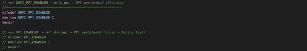
You also need to enable PPI module in sdk_config.h in order to use it. You do it by set NRFX_PPI_ENABLED 1 and comment out PPI_ENABLED, like so
Now we will look at common functions when working with PPI. A typical workflow include: allocating a PPI channel, assigning EEPs and TEPs, then enabling PPI channel. Let’s take a look at those APIs.
Allocating a PPI channel
First, you need to allocate a PPI channel. Remember in the previous section, we mentioned that there are 20 configurable PPI channels that you can use.
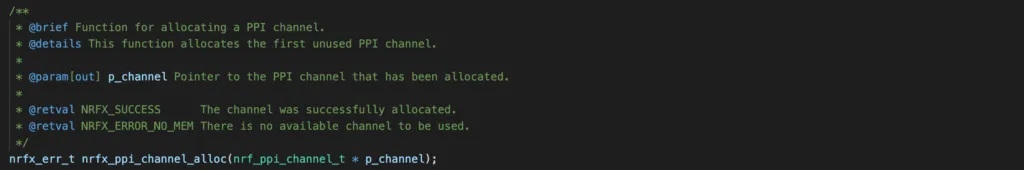
This function takes a pointer to the channel that has been allocated and returns NRF_SUCCESS if the allocation is successful. It returns NRFX_ERROR_NO_MEM if no channel is available to use.
Assigning task and event end points
To assign EEP and TEP to a PPI channel, you call nrfx_ppi_channel_assign() API:
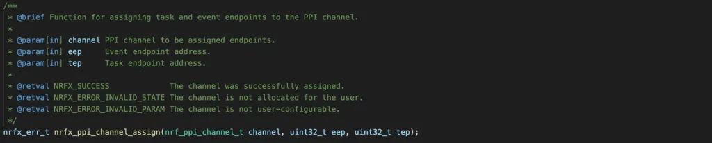
This function takes 3 arguments:
channelis the PPI channel that you allocated by usingnrfx_ppi_channel_alloc()eep: address of the event register that you want to connect totep: address of the task register at the other end of the PPI channel
You should make sure you get the return value of NRF_SUCCESS to ensure the assignment is successful.
Fork assign task end point
To add an additional task end point to the PPI channel, you use the function nrfx_ppi_channel_fork_assign()
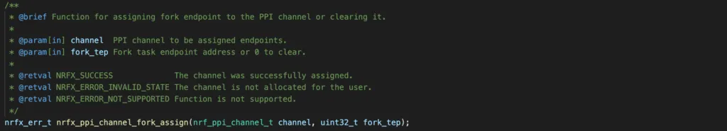
You will need to provide the PPI channel and the address of the task register that you want to fork assign.
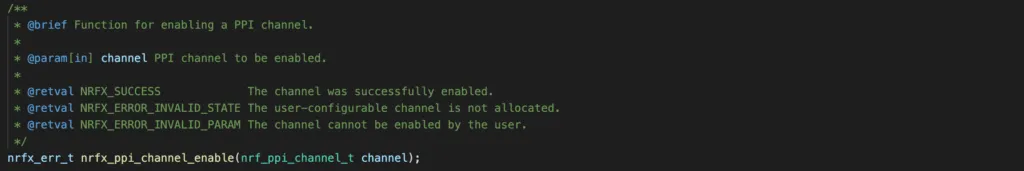
Enabling PPI channel
The last step of using PPI is to enable the channel using nrfx_ppi_channel_enable() and pass in the channel in the function argument.
PPI Project: Blink LED with TIMER/PPI/GPIOTE
To demonstrate PPI usage, we will build a simple project to blink a LED every 500 ms using PPI. In previous articles, we implemented the LED blinky project by using GPIO functions and simple delay, or use TIMER to generate interrupts and toggle GPIO insider interrupt service routine. Those approaches invoke CPU for toggling GPIO pin. In this example, we will see how to achieve the same thing without using any CPU resources, except for initial configuration.
Prerequisites
To follow along with this project, you will need a nRF52 development kit. I will use PCA10040 which has nRF52832 and a couple of LEDs for demonstrating. You will also need to download and install additional software packages to compile and flash the program to your target board.
Ideas
Here, I will explain the idea behind this project setup:
- We will configure a TIMER to generate an interrupt every 1 second. See previous article if you are not familiar with nRF52 TIMER.
- Once the timer expires, it will fire an event
EVENTS_COMPARE[0]which we will connect to one end of a PPI channel. - We will configure GPIOTE channel to control an output pin which connects to a LED. The GPIOTE channel has a
TASKS_OUTregister which can toggle the GPIO pin. - The GPIOTE’s
TASKS_OUTwill be connected to another end of the PPI channel. - Once TIMER’s event is generated, it will propagate through PPI channel and trigger
TASKS_OUTautomatically. This will make LED on and off repeatedly and achieve our goal.
Code
You can also see the full code of the project on Github.
How the code works
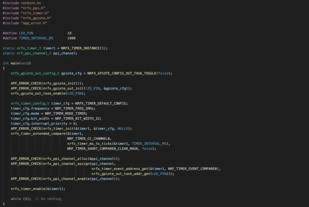
- First, we configure a GPIOTE channel to control the GPIO pin connect to a LED, in this project is pin 18. If you want to learn more about GPIOTE, check out previous post.
- Call
nrfx_gpiote_init()to initialise the GPIOTE module - Use function
nrfx_gpiote_out_init()to configure a GPIOTE channel to control an output GPIO pin usingOUTtask. Whenever theOUTtask is trigged, the GPIO output state is toggled. - You need to enable the GPIOTE channel by calling
nrfx_gpiote_out_task_enable()
- Secondly, setup a hardware timer to count 1 second interval. If you are unfamiliar with nrf52 hardware timers and the nrfx_timer driver, checkout our previous article.
- Use the macro
NRFX_TIMER_INSTANCE(1)to specify that you want to use hardware timer instance TIMER1. Note that you need to enable TIMER1 insdk_config.h. - Declare a variable
timer_cfgand specify its frequency, timer mode, bit width and interrupt priority. Then callnrfx_timer_init()to initialise the TIMER1 withtimer_cfgconfiguration. - Setup timer to generate an event
EVENTS_COMPARE[0]by usingnrfx_timer_extended_compare()API. Use the functionnrfx_timer_ms_to_ticks()to get the tick values for your defined interval. Note that you need to make sure the timer bit width is large enough to store the tick values, otherwise it will overflow too soon and you will not get an error. TheNRF_TIMER_SHORT_COMPARE0_CLEAR_MASKvalue enable SHORTS register so that the timer’s internal counter register is cleared once the event is generated, and timer will start counting from 0 again. - Enable timer by calling
nrfx_timer_enable()function. However, timer 1 should be enabled after PPI setup.
- Thirdly, configure a PPI channel so that when timer compare event happens, it will automatically trigger GPIOTE’s
OUTtask.
- You begin with allocating a PPI channel using API
nrfx_ppi_channel_alloc() - Then you assign TEP and EEP for the allocated PPI channel using
nrfx_ppi_channel_assign(). To get the event address of timer 1, you use the functionnrfx_timer_event_address_get()and to get the task address of GPIOTE channel, you usenrfx_gpiote_out_task_addr_get(). These functions will return 32-bit address of the task and event registers. - After that, you enable the PPI channel by calling
nrfx_ppi_channel_enable()
- After setting up GPIOTE channel, TIMER1, and PPI channel, you start the timer and go to the main loop. In the main loop, the CPU does nothing. When the timer interrupts, it will toggle
LED_PINand make it blinks without any CPU involvement.
Compiling and flashing the code
To compile and flash the program on to the nRF52 development board, open a terminal and type
make flashWhen flashing is completed, you should see the LED2 on the PCA10040 board blinks every second.
Full project files can be seen on Github.
Wrapping Up
In this article, you have learnt about the PPI module in nRF52 family. You learnt about nrfx_ppi driver and practice how to setup a project using PPI. If you have any comments, leave it in the comment section below.
Where to go from here
To learn more about PPI, check out the Nordic Infocenter which has full API reference.