· Nordic · 6 min read
Controlling nRF52 GPIO by tasks and events
The nRF52 family’s GPIO control is made even more powerful with the GPIOTE (General Purpose Input/Output Tasks and Events) peripheral, which allows you to configure GPIOs to trigger actions based on tasks and events. In this article, we’ll dive into the capabilities of the GPIOTE peripheral and explore how to use the nrfx_gpiote driver to interact with it. You’ll learn how to configure input and output pins, set up event-driven GPIO tasks, and handle interrupts efficiently. With a practical example, we’ll show you how to use GPIOTE to control LEDs, detect button presses, or trigger other peripherals, all while optimizing CPU usage for real-time applications.
Introduction
In previous article, I have introduced APIs to control GPIO ports of nRF52 using nrf_gpio.h driver in nRF5 SDK. There’s another way to interact with digital I/O ports of nRF52 which involves tasks and events. In this article, I will discuss the GPIOTE (G eneral P urpose I nput O utput T asks and E vents) peripheral in nRF52. I will talk about:
- Why you might want to use GPIOTE in your project
- GPIOTE registers
- The
nrfx_gpiotedriver in nRF52 SDK to interact with GPIOTE - How to include
nrfx_gpiotein your project - Some commonly used APIs in
nrfx_gpiotelibrary - Build a project using GPIOTE to control digital input and output ports
To compile and run your code on real nRF52 hardware, it is recommended that you have a nRF52 development kit such as
Affiliate Disclosure: When you click on links in this section and make a purchase, this may result in this site earning a commission at no extra cost to you.
GPIOTE peripheral
The GPIOTE peripheral in nRF52 provides a way for accessing GPIO pins using tasks and events. Here are some reasons why would you might want to use GPIOTE in your project:
- Using tasks and events allow a peripheral to trigger another peripheral without CPU intervention, hence you can use GPIOTE (in combination with PPI) to implement interesting low power applications.
- GPIOTE can generate interrupt when an event happens. You can connect a GPIO pin to a GPIOTE channel and configure it to generate an interrupt on the GPIO pin state change.
GPIOTE is a peripheral which has 8 channels. Each channel can be configured to connect to a GPIO pin.
If a GPIOTE channel is connected to a GPIO Input Pin, it can generate events on the input state change (rising edge, falling edge or any change).
GPIO Input Pin ---> GPIOTE Channel ---> Events
If a GPIOTE channel is connected to a GPIO output pin, it can control its digital output (e.g. drive it low or high). This is done by writing to a GPIOTE task register.
GPIOTE Output Pin <--- GPIOTE Channel <--- Tasks
Configuration registers
CONFIG[0], ..., CONFIG[7]: These registers configures GPIOTE channel 0 to 7, respectively, including:- Mode: To configure GPIOTE channel in event mode or task mode. Use event mode when GPIOTE channel is connected to an input pin, and use task mode when GPIOTE Channel is connected to an output pin.
- GPIO pin: to select which GPIO pin is connected to the GPIOTE Channel.
- Initial value of GPIO pin when in task mode
- Configure operation in task mode when
OUTtask is triggered. TheOUTtask can set, clear or toggle an output pin. When writing toOUTtask register, the operation that will be performed depending onCONFIGregister. - Configure operation in input that will trigger
INevent in event mode
Event registers
EVENTS_IN[0], ..., EVENTS_IN[7]: these 32-bit event registers are updated when an event happens in a GPIOTE channel 0, …, 7, respectively. These registers are used when a GPIOTE channel is connected to an input GPIO pin. An event may be generated when the input pin goes from low to high, high to low, or both. TheCONFIGregister determines when an event is generated.
Task registers
TASKS_SET[0], ..., TASK_SET[7]: TheseSETtask registers are used to set a GPIO output pin that is connected to a GPIOTE channel. Writing to these registers to set the output port high.TASKS_CLR[0], ..., TASKS_CLR[7]:CLRtask registers will clear the GPIO output pin that is connected to the GPIOTE channel when written to.TASKS_OUT[0], ..., TASKS_OUT[7]: TheseOUTtask registers will trigger an operation (e.g. Set, Clear or Toggle an output pin). The specific operation that happens depends on the settings inCONFIGregister.
Interrupt registers
INTENSET: enable interrupt when an event happensINTENCLR: disable interrupt when an event occurs
The nrfx_gpiote driver
In the previous section, we described the GPIOTE hardware and its internal registers. To control the GPIOTE peripheral, you use the nrfx_gpiote driver from nRF5 SDK. In this section, we discuss how to include the driver in your project and some common APIs from the library.
Include nrfx_gpiote driver in your project
To include nrfx_gpiote driver in your project, you need to add nrfx_gpiote.c in your source file list
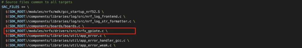
and include nrfx_gpiote.h header file defined in $(SDK_ROOT)/modules/nrfx/drivers/include.
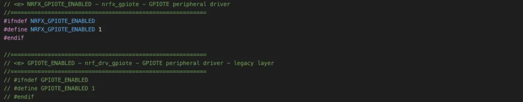
Enabling GPIOTE peripheral in sdk_config.h
To use GPIOTE peripheral, you need to enable it in sdk_config.h by setting NRFX_GPIOTE_ENABLED to 1
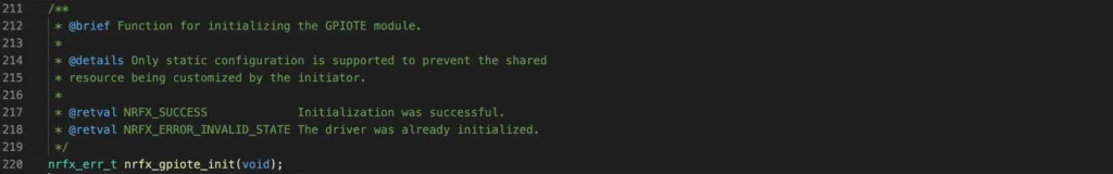
Initialise GPIOTE driver
Before using the driver, you need to initialise it. To initialise the driver, you call nrfx_gpiote_init() function:
Configure GPIOTE for an input pin
Use the function nrfx_gpiote_in_init() to configure a GPIOTE channel to connect to an input I/O pin and to generate an interrupt on pin state change.

This function takes 3 arguments:
pin: The GPIO pin that should be connected to a GPIOTE channelp_config: a pointer that points to a configuration structure which specifies the conditions to trigger interrupt and whether to use internal pull up or pull down resistors on the GPIO pin.evt_handler: a callback function that executes when interrupt occurs.
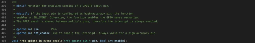
Enabling GPIOTE input pin
After configuring the GPIOTE input pin, you need to call nrfx_gpiote_in_event_enable() to enable it
Configure GPIOTE for an output pin
To configure a GPIOTE channel to connect to an output pin, use the function nrfx_gpiote_out_init():
![]()
This function takes 2 parameters:
pin: the GPIO pin that should be connected to a GPIOTE channelp_config: a pointer that points to a configuration structurenrfx_gpiote_out_config_t. You can use the following macros for the configuration:NRFX_GPIOTE_CONFIG_OUT_TASK_LOWNRFX_GPIOTE_CONFIG_OUT_TASK_HIGHNRFX_GPIOTE_CONFIG_OUT_TASK_TOGGLE
Enabling GPIOTE output pin
After configuring the GPIOTE output pin, you need to enable it by calling nrfx_gpiote_out_task_enable()

Manually triggering GPIOTE OUT task
To trigger GPIOTE OUT task manually, call API nrfx_gpiote_out_task_trigger()

This function will trigger OUT task, and will set, clear or toggle the output pin connected to the GPIOTE channel based on GPIOTE channel configuration.
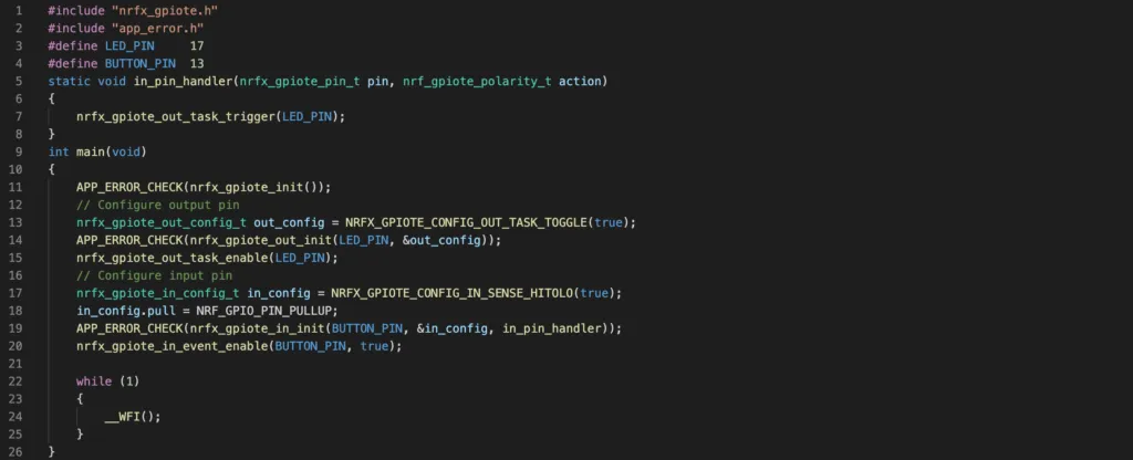
NRF52 GPIOTE Project Example
In this section, you will implement a project using GPIOTE to control digital input and output ports. The objective of the project is to toggle a LED whenever you press a button:
- Initially, the button is not pressed, and LED is off
- When you press the button the first time, the LED is turned on.
- If you press the button second time, the LED is shutdown, and so on.
By going through this simple project, you will learn how to use nrfx_gpiote APIs to configure a GPIOTE channel to control an output port (control LED), and uses a GPIOTE channel to trigger an interrupt on an input pin state change (detect button pressed).
Code
The above task can be implemented with the following code
The full project files can be seen here.
Wrapping Up
In this article, you have learnt about the GPIOTE peripheral of nRF52 and the APIs in nrfx_gpiote driver to interact with it. You aslo learnt how to implement a practical project that uses GPIOTE to control digital input and output ports. Thanks for reading.