· Nordic · 5 min read
Controlling NRF52 GPIO with nRF5 SDK
The GPIO (General Purpose Input/Output) ports on the nRF52 series are essential for interfacing with external components like sensors, LEDs, and buttons. In this guide, you’ll learn how to control the digital input and output ports of the nRF52 family using the nRF5 SDK. We’ll walk you through configuring GPIO pins as inputs or outputs, reading button states, and toggling LEDs. With practical examples and code snippets, you’ll gain the skills to easily interact with your hardware and create responsive embedded systems.
Introduction
Controlling digital ports, such as blink an LED or read a button state input, are basic tasks which you need to learn when working with any chip platform. However, if you are a beginner to nRF52 development, there isn’t any simple guide in nRF5 SDK to help you get started. The most simple example in nRF5 SDK is the blinky project which uses bsp library and is difficult to digest for new comers. That’s why I write this guide to help you learn nRF52 General Purpose Input Output (GPIO) usage with nRF5 SDK.
In this article, you will learn:
- API functions to control GPIO ports in nRF5 SDK
- How to configure a pin as an input or an output port
- How to set or clear a pin, how to read digital input from an I/O pin
- Write code to blink an LED and detect when a button is pressed
To compile and run your code on real nRF52 hardware, it is recommended that you have a nRF52 development kit such as
Affiliate Disclosure: When you click on links in this section and make a purchase, this may result in this site earning a commission at no extra cost to you.
NRF52 GPIO functions
To control GPIO ports, you use API functions provided by Nordic nRF5 SDK. The functions that we are interested in are defined in nrf_gpio.h header file and you need to include this library to use it.
Control Digital Output Pins
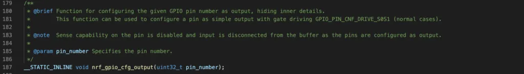
To set a pin as an output port, you use the function nrf_gpio_cfg_output() and specify the pin number:
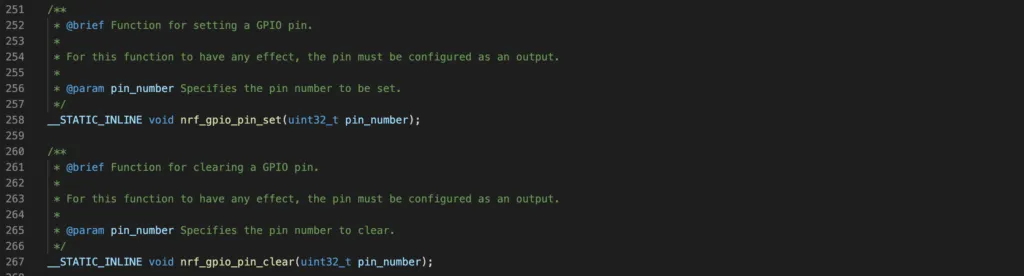
To set a pin high or clear a pin (set a pin low), you use the functions nrf_gpio_pin_set() and nrf_gpio_pin_clear(), respectively:
Read Digital Input Pins
First, you will need to configure a pin as input port using the function nrf_gpio_cfg_input()
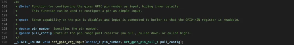
pull_config is a parameter to determine whether to use internal pull up/down resistors and can take one of 3 possible values NRF_GPIO_PIN_NOPULL, NRF_GPIO_PIN_PULLDOWN, or NRF_GPIO_PIN_PULLUP.
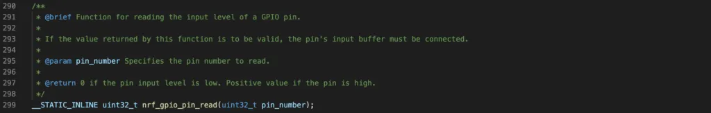
After that, use function nrf_gpio_pin_read() to get the digital input value
NRF52 GPIO Project Example
To demonstrate the usage of above API functions, you will build a simple project that can run on the PCA10040 development board. On the PCA10040 board, there are 4 buttons, labeled from button 1 to button 4, and 4 LEDs, labeled from LED 1 to LED 4 that you can use. In the project, pressing button 1 will light up LED 1, and when button 1 is not pressed, LED 1 is turned off.
Hardware
You need to identify the GPIO pin of nRF52832 that is connected to button 1 and GPIO pin that is connected to LED 1 by looking into the schematic of nRF5-DK that can be found on Nordic’s website. The following simplified diagram shows the buttons and LEDs and their connections with nRF52832 chip pins.
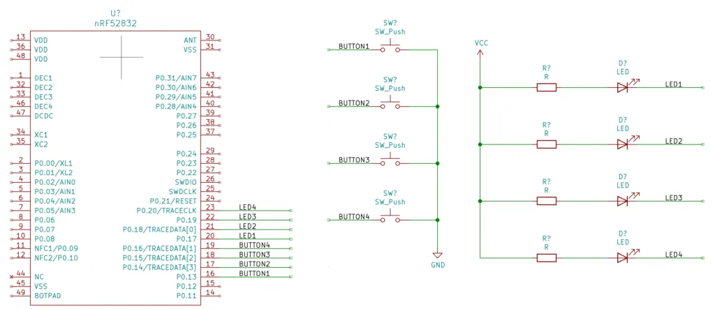
You will need to enable internal pull up resistor on the button pins. When a button is not pressed, the value you read from respective GPIO pin is high. On the other hand, when the button is pressed, the respective GPIO pin is pulled to ground and you would get 0 when reading that pin. The LEDs are active low, meaning if you set GPIO pins that are connected to LEDs low, the LEDs will turn on. If you set those pins high, the corresponding LEDs are turned off.
Code
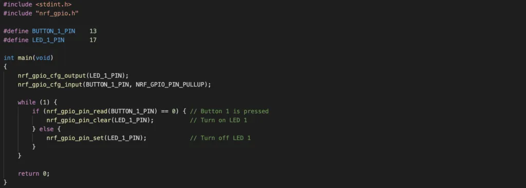
The following code performs the task described previously
How the code works
The above code is almost self-explanatory.
- You first include necessary libraries, in this case, we include
nrf_gpio.hand system librarystdint.h. - Then, you use define the GPIO pins that are connected to button 1 and LED 1, which are GPIO pin 13 and 17, respectively.
- In the main function, you configure the LED 1 pin as output pin using function
nrf_gpio_cfg_output()and configure button 1 pin as input with internal pull up resistor usingnrf_gpio_cfg_input()APIs. - In the main loop, you repeatedly read the digital input of button 1 to determine if it is pressed or not by calling
nrf_gpio_pin_read()function. If it is pressed, turn on LED 1 by clearing GPIO pin 17. Otherwise, turn off LED 1 by setting GPIO pin 17. Clearing or setting LED 1 pin is done by callingnrf_gpio_pin_clear()andnrf_gpio_pin_set(), respectively.
Compile and flash the program
To compile and flash the above program to the nRF52-DK board, follow instructions in the previous article. You will need to install a number of tools, including nrfjprog to flash the code on the target hardware. After flashing the code, you should see that when button 1 is pressed, LED 1 is turned on and when button 1 is not pressed, LED 1 is turned off.
Wrapping Up
Simple things do not need to be complicated. Maybe all you need is just a simple project to get your hand wet and start your journey to nRF52 development world. This guide provide you just that.