· Nordic · 9 min read
nRF52 TIMER peripheral and nrfx_timer driver
Timers are essential for managing time-based events in embedded systems, and the nRF52 series offers powerful TIMER peripherals to handle such tasks efficiently. In this article, we’ll explore the TIMER peripheral in the nRF52 family and how to utilize the nrfx_timer driver from the nRF5 SDK. You’ll learn how to configure the timer for various use cases, including periodic tasks, timeouts, and event generation. With a hands-on example, we’ll guide you through initializing a timer instance, setting up interrupts, and using the timer for precise timing control — all while minimizing CPU overhead.
Introduction
Timer is a basic peripheral that is found in most microcontrollers and is used in many different applications. Being familiar with timer and its usage are essential when working with any chip platform. In this article, you will learn about the nRF52 TIMER peripheral and how to control it using the nrfx_timer driver in nRF5 SDK. The topics we cover include:
- Block diagram, instantiations and registers of nRF52 TIMER peripheral
- The
nrfx_timerdriver and how to include it in your project - nRF52 TIMER APIs: initialise, start, stop, configure a timer in extended compare mode
- Projects demonstrating TIMER usage
To compile and run your code on real nRF52 hardware, it is recommended that you have a nRF52 development kit such as
Affiliate Disclosure: When you click on links in this section and make a purchase, this may result in this site earning a commission at no extra cost to you.
The nRF52 TIMER peripheral
Block diagram
In this section, we will talk about the TIMER peripheral of the nRF52 family. Let’s have a look at its block diagram first. The diagram below is taken from nRF52832 datasheet and shows internal components of a TIMER:
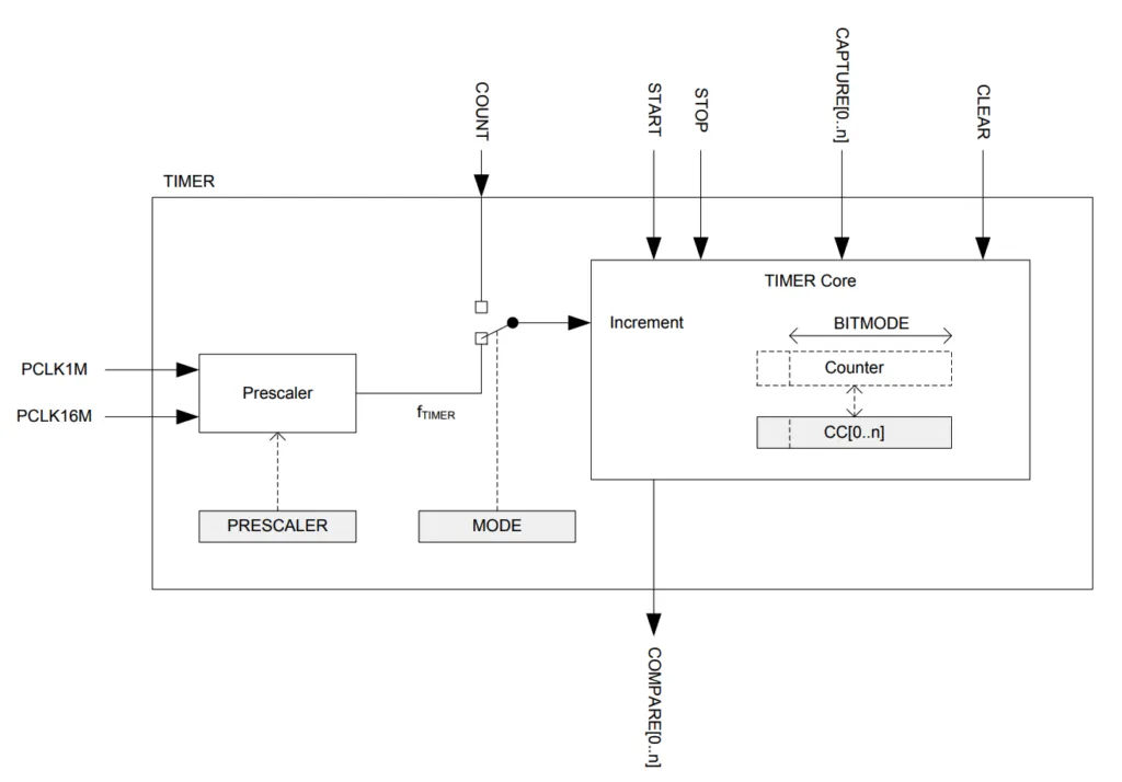
As can be seen from the diagram, a TIMER consists of a TIMER core, which has an internal counter register. Depending on mode of operation, the internal counter register is increased by 1 every clock cycle (timer mode), or by triggering COUNT task (in counter mode). The mode of operation is determined by MODE register. If the timer is running in timer mode, the internal counter register increases by 1 every T seconds where T is determined by the timer frequency f (Hz)
T = 1 / fand
f = 16 MHz / (2 ^ PRESCALER)The value stored in PRESCALER register determines which frequency the timer runs on. For example, if PRESCALER = 1, the timer runs on 16 MHz frequency, the time interval between timer tick would be 1 / 16 MHz = 62.5 ns
Registers
All nRF52 peripherals are allocated 1024 registers, each register is 32 bit wide. These registers are accessible with an address offset in relation with the base address of the peripheral. For example, the nRF52832 TIMER0 instance has a base offset of 0x40008000. Its TASK_COUNT register has an offset of 0x008, or absolute address of 0x40008008. In this section, I describe the registers of a TIMER peripheral.
Task registers : these registers are used to trigger an action. When a register is written a value of 1, the corresponding action is triggered.
START: start the TIMER.STOP: stop the TIMERCOUNT: increase the internal Counter register value by 1 in Counter modeCLEAR: clear the current value of internal Counter registerCAPTURE[0], CAPTURE[1], CAPTURE[2], CAPTURE[3], CAPTURE[4], CAPTURE[5]: these capture registers are used to copy the current value of internal Counter register to respectiveCC[0], CC[1], CC[2], CC[3], CC[4], CC[5]registers.
Event registers : Event registers are used to signify that something has happened.
COMPARE[0], COMPARE[1], COMPARE[2], COMPARE[3], COMPARE[4], COMPARE[5]: These event registers are updated when the value of internal Counter register is equal to one of the respective CC registers.
Other registers
CC[0], CC[1], CC[2], CC[3], CC[4], CC[5]: These Capture/Compare registers can be used for two purposes: to store value of internal Counter register whenCAPTUREtask is triggered, or to use as a reference to generateCOMPAREevent when their stored value is equal internal Counter registerBITMODE: is to specify the number of bits used by the internal Counter register.SHORTS: this is is a 32-bit register which is used to enable/disable triggering a task when an event happens. There are 6COMPAREx_CLEARbits inSHORTSregister which could be configured to triggerCLEARtask whenCOMPARExevent occurs. There are also 6COMPAREx_STOPbits, which could be configured to triggerSTOPtask whenCOMPARExevent happens.INTENSETandINTENCLEAR: These registers are used to enable/disable interrupts when a compare event happens. Individual compare event interrupt can be enabled or disabled by using respective bit in the registers.
Instances
Instances are copies of the same peripheral. There are 5 TIMER instances in nRF52832, named from TIMER0 to TIMER4. The table below listed these instances and their respective base addresses:
| Timer instance | Base address |
|---|---|
| TIMER0 | 0x40008000 |
| TIMER1 | 0x40009000 |
| TIMER2 | 0x4000A000 |
| TIMER3 | 0x4001A000 |
| TIMER4 | 0x4001B000 |
If you are using a different chip, check the chip’s datasheet to see how many instances they have.
The nrfx_timer driver
When writing nRF52 applications using TIMER peripheral, you normally won’t need to interact directly with its registers directly. The nrfx_timer driver in nRF5 SDK hides register interaction details and provides APIs to control TIMER peripheral in nRF52. Note that in nRF5 SDK, there’s another library called app_timer which uses Real Time Counter 1 (RTC1) peripheral to create multiple timer instances. In this tutorial, we are working with the nrfx_timer library and hardware timer instances.
You can see that in nRF5 SDK examples folder, nrf_drv_timer is being used instead of nrfx_timer. You might be wondering what are the differences between nrfx_timer and nrf_drv_timer drivers. The nrf_drv_timer library is a legacy driver, used in previous SDK versions. Although it is recommended to use the newer nrfx_timer driver, Nordic’s documentation and examples have not been updated and still use nrf_drv_timer library. This might cause a little confusion.
Include nrfx_timer driver in your project
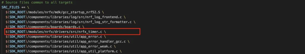
To use nrfx_timer driver, you need to include nrfx_timer.h header file and add nrfx_timer.c to your source file list
Enabling timer instance in sdk_config.h
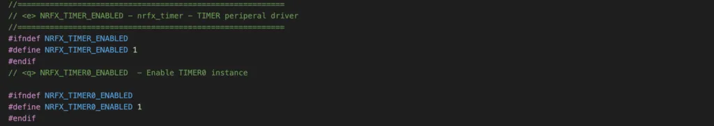
When working with nRF52 hardware timer instances, you need to enable them in sdk_config.h. You will get compilation errors if you don’t enable them. Let’s say you want to use TIMER0 instance, you have to enable it by setting NRFX_TIMER_ENABLED and NRFX_TIMER0_ENABLED to 1.
Initialisation
To initialise a TIMER, you use function nrfx_timer_init().

This function takes a few arguments:
p_instance: is a pointer that points to TIMER instance being usedp_config: is a pointer that points to TIMER configuration. This configuration defines how to TIMER should operate, such as its frequency, bit mode, timer mode, and other parameters.timer_event_handler: is a callback that executes when timer interrupts happen. You can passNULLif no interrupt handler is being used.
This function returns NRF_SUCCESS if the TIMER is initialised successfully and returns NRFX_ERROR_INVALID_STATE if the instance has already initialised.
Start a TIMER
To start a TIMER, call the API nrfx_timer_enable() and pass in the pointer to the timer instance.

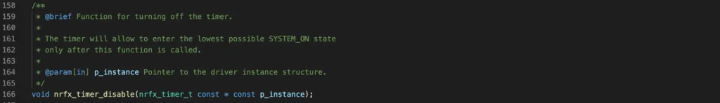
Stop a TIMER
To stop a TIMER, call nrfx_timer_disable() and pass in the pointer to the timer instance.
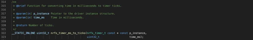
Converting time in ms to timer ticks
In order to configure the timer to count for a certain period, you need to specify a value to store in a compare register. This value is dependant on the timer frequency and prescaler register value. There’s a function nrfx_timer_ms_to_ticks() to do the conversion between milliseconds and timer ticks that you can use, so you don’t need to do manual calculation yourself. Use this function and pass in the pointer to timer instance, and value in millisecond. It will return the timer ticks value to store in one of compare registers.
Configure a timer in extended compare mode
To configure a timer in extended compare mode, use the API nrfx_timer_extended_compare().

This function takes a few arguments:
p_instanceis the pointer that points to timer instance being usedcc_channelis the compare channel to use. As seen in previous section, there are 6 channels you can use, from 0 to 5. You can pass inNRF_TIMER_CC_CHANNEL0toNRF_TIMER_CC_CHANNEL5.cc_valueis the compare value. This is the value to store in the compare register so that when internal Counter register value is equal it, a compare event is generated.timer_short_mask: use this argument to specify whether to use short register to trigger a task automatically when an event happens. For example, if you pass inNRF_TIMER_SHORT_COMPARE0_STOP_MASK, when COMPARE[0] event is generated, the timer is also stopped.enable_int: to specify whether an interrupt is enabled or disabled.
NRF52 TIMER Project Example s
To demonstrate TIMER usage, in this section, we will build several practical projects using TIMER.
Project 1: Using nRF52 TIMER in timer mode to blink an LED
In this first example, our objective is to build a simple project that uses a TIMER peripheral to generate a periodic interval. The TIMER will generate an interrupt every 500 ms. When the timer expires, we toggle a GPIO pin that control a LED, so that it makes the LED blink.
Code
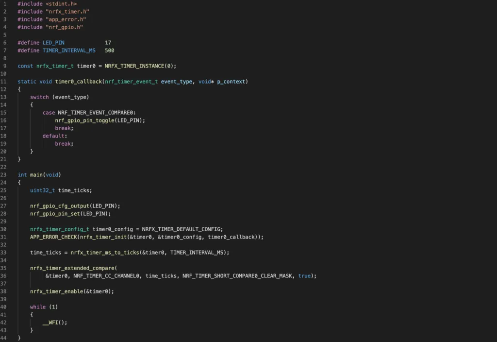
Full code of the project can be seen on Github here. Note how we use timer APIs described in previous section to build this project.
Project 2: Using nRF52 TIMER in counter mode
In this example, we will configure TIMER0 in counter mode to count the number of time a button is pressed. We will be using PCA10040 board in our example. As mentioned in our previous tutorial, the PCA10040 has 4 LEDs and 4 buttons. We will use button 1 which is connected to GPIO pin 13 and LED 1 to LED 4. Whenever button 1 is pressed, the internal counter register is increased by 1. The maximum value can be stored in internal counter register value is 15. The LED 1 to LED 4 will display the current value of the internal counter register.
This project involves a number of steps to setup:
- First, you need to configure pin 13 as GPIO input pin with internal pull up register as described in basic GPIO usage article.
- Then you need to initialise the timer in counter mode, configure the timer so that when it counts to 6, its internal counter register will be reset to 0 again. To do this, you can use the SHORT register to clear the register value when its internal counter register is equal to value stored in COMPARE0 register.
- You also need a function to read the value of internal counter register and display it on LED 1 to LED4.
- In the main loop, you continuously detect whether button 1 is pressed. If yes, you trigger the timer’s COUNT task so that its internal register value is updated. Then you read the internal counter register value and display it on the LEDs.
You can see the full code here.
Note that in this project, we have used the timer APIs nrfx_timer_increment(). This function will trigger the COUNT task so that internal counter register is increased by 1 each time button 1 is pressed.
nrfx_timer_increment(&timer0);To get the timer’s current value, we use CAPTURE1 register to copy the value from internal counter register, then use the return value of function nrfx_timer_capture()
timer_value = nrfx_timer_capture(&timer0, NRF_TIMER_CC_CHANNEL1);Wrapping Up
In this article, you have learnt about the hardware timer modules of the nRF52. You also learnt about APIs in nrfx_timer driver to control timer instances and implemented a simple project using timer to blink an LED. Thank you for reading.