· Nordic · 7 min read
Measuring analog signal with NRF52 SAADC
Need to capture analog data on your nRF52? The SAADC (Successive Approximation Analog-to-Digital Converter) peripheral is your go-to for accurate, low-power analog signal measurement. In this article, we’ll break down the key features of the nRF52’s SAADC, including its differential mode, oversampling, and EasyDMA support. We’ll also walk through setting up the nrfx_saadc driver — part of the modern nrfx HAL — to configure channels, handle conversions, and read ADC values with minimal CPU load. With a practical example included, you’ll be up and running with analog data collection in no time.
Introduction
To measure input signals with a microcontroller, you often need to use Analog to Digital Conversion module. In nRF52, this module is called SAADC or Successive Approximation Analog to Digital Conversion. In this article, I will show you how to use the nRF52 SAADC peripheral by implementing a simple project. I will talk about:
- nRF52 SAADC pins, operation modes and conversion results
- The nrfx_saadc driver to control SAADC and its APIs
- How to add nrfx_saadc driver to your project and configure SAADC parameters
- A sample project using SAADC
To compile and run your code on real nRF52 hardware, it is recommended that you have a nRF52 development kit such as
Affiliate Disclosure: When you click on links in this section and make a purchase, this may result in this site earning a commission at no extra cost to you.
The nRF52 SAADC peripheral
To use SAADC, some basic knowledge about the hardware block is required. In this section, we will look at main features of nRF52832’s SAADC module and important things you need to know when working with SAADC.
Analog input pins
There are many I/O pins in nRF52832, however, not all pins can be used as analog inputs. There are 8 GPIO pins that can be configured as analog input which are listed in the table below. You can only use one or more of the pins in the table to measure analog input in your projects. If you are using a different chip, such as nRF52840, you’ll need to check its datasheet to see which pins are analog input pins.
Analog pin  GPIO pin
AIN0        P0.02
AIN1        P0.03
AIN2        P0.04
AIN3        P0.05
AIN4        P0.28
AIN5        P0.29
AIN6        P0.30
AIN7        P0.31
SAADC can be configured to measure voltage between one of the analog pin and ground, called a single-ended channel. There are up to 8 single-ended channels corresponding to 8 analog input pins. It can be also configured to measure the potential difference between two analog pins, for instance, between AIN0 and AIN1. If configured this way, there are up to 4 differential channels.
Operation modes
The SAADC can be configured to take sample from one channel at a time (one shot conversion mode), or measure multiple channels in sequence (scan mode). Sampling can be triggered via a task from software or through a PPI channel. Conversion results can be written to RAM directly (instead of storing in registers) using EasyDMA block.
Conversion result
The result of the sampling is calculated by
RESULT = [V(P) - V(N)] * GAIN / REFERENCE * (2 ^ (RESOLUTION - m))or
V(P) - V(N) = RESULT * REFERENCE / GAIN / (2 ^ (RESOLUTION - m))where V(P) and V(N) are the voltage at positive and negative pins, respectively (for single-ended channel, V(N) = 0). GAIN is the gain setting of the SAADC, REFERENCE is the reference voltage, RESOLUTION is the number of bits (8/10/12). m is equal 0 if single-ended mode and is equal 1 if differential mode. This formula is important as the SAADC does not provide measured values in milivolt directly.
Let’s take an example. Supposed SAADC is configured in single-ended mode to measure voltage at AIN0 pin. If we use GAIN value of 1/6 and internal reference voltage of 0.6V and 10 bit resolution, the formula to calculate the voltage at AIN0 will be
V(AIN0) = RESULT * (0.6) / (1/6) / (2^10)
V(AIN0) = RESULT * 3.6 / 1024 (Volt)
V(AIN0) = RESULT * 3600 / 1024 (mV)
V(AIN0) = RESULT * 225 / 64 (mV)
This means if we take the result, multiply it with 225 and right shift by 6, we will get the voltage at AIN0 pin.
The nrfx_saadc library
To control the SAADC, you use the driver nrfx_saadc or nrf_drv_saadc in nRF5 SDK. In this section, we will look at how to include the driver, how to enable the SAADC and configure its parameters.
Including the nrfx_saadc driver
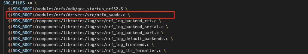
To add the driver to your project, you need to add nrfx_saadc.c file in source file list so that the library’s functions are compiled. Then include the header file nrfx_saadc.h before making calls to its functions.
Enabling the SAADC in sdk_config.h
As explained in previous articles, nRF52 project use a configuration file named sdk_config.h to store all peripherals’ definition and their parameters. By placing them in one place, it is a little easier to manage the project. Some internal functions in the nrfx_saadc driver will check if these definitions are present and will throw an error during compilation if they are not found. Therefore, before using SAADC, you need to add a definition in sdk_config.h to enable it as following:

Note that you will need to remove SAADC_ENABLED 1 in sdk_config.h if it presents because in apply_old_config.h, NRFX_ definitions will be overridden.
Setting SAADC default parameters
In sdk_config.h, you can also set default parameters for SAADC. For example, to use 10-bit resolution, you change NRFX_SAADC_CONFIG_RESOLUTION to 1, or to use 12-bit resolution, set that parameter to 2.
Initialisation
The SAADC needs to be initialised before using. You call nrfx_saadc_init() to initilise the peripheral.
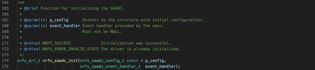
This function takes two arguments. The first argument is a pointer to a configuration structure which specifies the SAADC’s parameters such as resolution, oversample, interrupt priority and whether low power mode is active. The second argument is an event handler which is called when SAADC events are generated. If you don’t handle SAADC events, you still need to provide an empty handler.
Channel initialisation
The next step is to initialise a channel that you want to use by calling nrfx_saadc_channel_init().
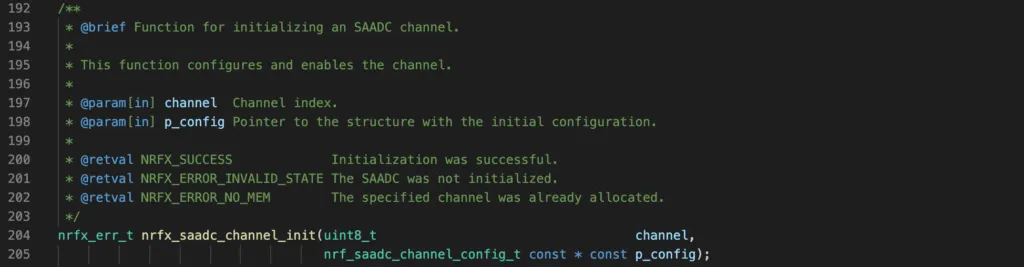
Remember in previous section that we need to specify which analog pins are used, whether to use single-ended mode or differential mode, and other parameters such as gain, reference voltage, acquisition time. You can use some macros provided by the driver, for instance, NRFX_SAADC_DEFAULT_CHANNEL_CONFIG_SE(PIN_P) to define a configuration for single ended mode, or NRFX_SAADC_DEFAULT_CHANNEL_CONFIG_DIFFERENTIAL(PIN_P, PIN_N) to define a differential mode.
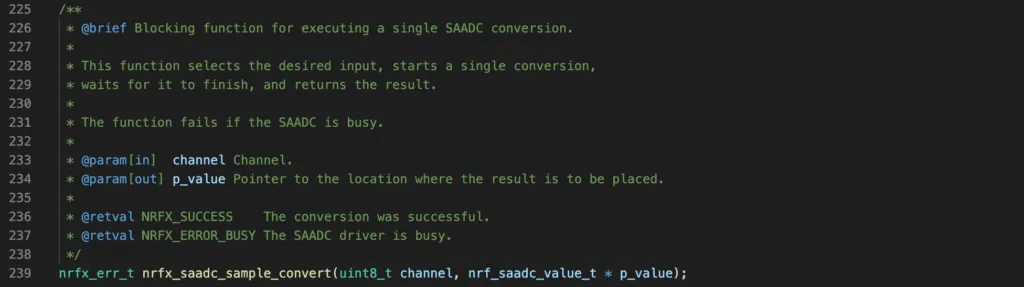
Convert a sample in one channel in blocking mode
To convert a sample in blocking mode, use the function nrfx_saadc_sample_convert(). This function will perform conversion in the channel as specified in the first argument and wait for conversion to finish, then return. The value of the conversion is stored at address pointed by p_value.
Setup sampling in non-blocking mode
The SAADC can be setup in non-blocking mode, meaning the calling function will return immediately. The function nrfx_saadc_buffer_convert() is used to setup a buffer for storing ADC conversion results in RAM. This function takes two arguments: a pointer to the result buffer in RAM and the size of the buffer in words. This function only sets the buffer, but does not trigger the conversion. To trigger the conversion, one needs to call nrfx_saadc_sample() to start the conversion.
nRF52 SAADC Sample project
Now you have learnt common functions when working with SAADC. In this section, we will implement a simple project using SAADC to demonstrate. In this project, we will use SAADC to sample an analog pin using single channel and one shot mode. We will use nRF52 development board PCA10040 with nRF52832, and use the NRF_LOG module to print out measured values to console via RTT.
Code
Add the following code to your main.c file
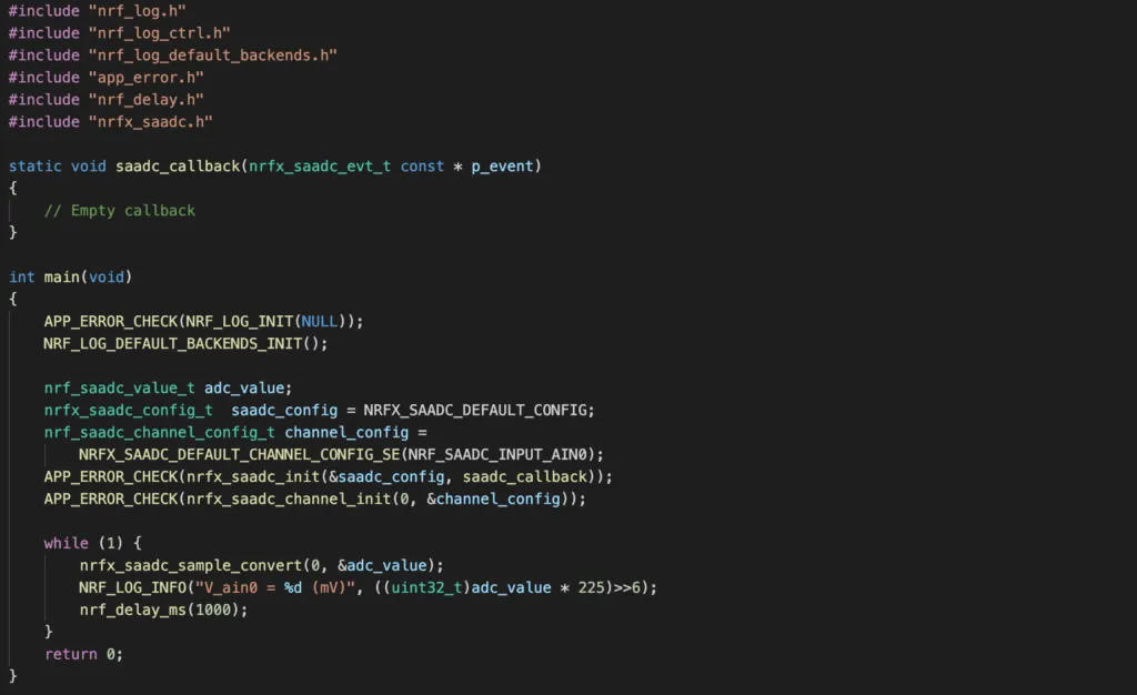
The code above will setup the SAADC in single-ended mode to sample analog input pin AIN0. It will use default parameters: gain of 1/6, use internal reference 0.6V and 10-bit resolution. It performs conversion in blocking mode, then prints out the value to RTT console, and wait 1 second before repeating again. As explained earlier, the raw value is multiplied with 225 and right shift 6 bits to get the milivolt values.
Wrapping Up
You have seen a minimal example using SAADC in this article: single conversion, one at a time on one analog pin. From this example, hopefully you gain some basic understanding of SAADC so that you can explore more complicated scenarios, for example, using a PPI task for triggering SAADC. If you want to go further from here, Nordic Infocenter and nRF5 SDK examples are good places to go. Thanks for reading.