· Esp32 · 5 min read
ESP32 as I2C Master Tutorial (ESP-IDF)
The ESP32 is highly versatile and supports multiple communication protocols, including I2C. In this tutorial, we’ll guide you through configuring the ESP32 as an I2C Master using the ESP-IDF framework. You’ll learn how to initialize the I2C bus, set up the communication parameters, and send/receive data between the ESP32 (I2C Master) and an I2C Slave device. With clear examples, we’ll demonstrate how to communicate with common I2C peripherals like sensors or EEPROMs, giving you the foundation to integrate I2C devices into your ESP32-based projects.
Introduction
I2C (or Inter-Integrated Circuit) is a common protocol used in embedded system where two devices communicate with each other, one acts as a master and one behaves as a slave. This article shows you how to use the I2C driver in ESP-IDF to configure ESP32 as a master device to communicate with an I2C slave device.
ESP-IDF I2C APIs
I2C driver
The I2C driver header file is defined in driver/include/driver/i2c.h and you need to include the driver before using its APIs:
#include "driver/i2c.h"I2C Ports
ESP32 has two I2C hardware modules (or I2C ports) that facilitate I2C communication which are called I2C_NUM_0 and I2C_NUM_1. You can use either of these instances in your project. The SCL and SDA pins of these instances are not hard-wired to any specific GPIO pin. They are mapped to physical GPIO pins through software configuration.
Initialisation
The first step when working with I2C driver in ESP-IDF is to configure the driver by calling i2c_param_config() function
esp_err_t i2c_param_config(i2c_port_t i2c_num, const i2c_config_t *i2c_conf)This function configures the I2C port i2c_num with parameters stored in a configuration structure pointed by i2c_conf. Essentially, you need to specify which I2C instance you want to use, which pins are used as SCL and SDA, whether to enable pull up resistors on those pins and the clock speed of the instance. The following code snippet shows an example of configuring I2C_NUM_0 instance as I2C master, using GPIO pin 21 as SDA, pin 22 as SCL with pull up resistor enabled and 400 kHz clock speed.
i2c_config_t conf = {
	.mode = I2C_MODE_MASTER,
	.sda_io_num = 21,
	.scl_io_num = 22,
	.sda_pullup_en = GPIO_PULLUP_ENABLE,
	.scl_pullup_en = GPIO_PULLUP_ENABLE,
	.master.clk_speed = 400000,
};
i2c_param_config(I2C_NUM_0, &conf);
After configuring the I2C port, it needs to be activated by calling i2c_driver_install() function. The following snippet shows how to enable the I2C_NUM_0 port with the configuration above
i2c_driver_install(I2C_NUM_0, I2C_MODE_MASTER, 0, 0, 0);Sending data to I2C slave
To send data to an I2C slave, use the function i2c_master_write_to_device(). Note that this function is only available from ESP-IDF version 4.4. For earlier ESP-IDF versions, you have to call a number of APIs in sequence, such as i2c_cmd_link_create(), i2c_master_start(), i2c_master_write_byte() etc.
esp_err_t i2c_master_write_to_device(i2c_port_t i2c_num, uint8_t device_address,
const uint8_t *write_buffer, size_t write_size, TickType_t ticks_to_wait);
You need to tell this function which I2C port you want to use, the slave address, the buffer storing data you want to send and timeout value in ticks.
Receiving data from I2C Slave
To receive data from an I2C slave, use the API i2c_master_read_from_device() which is available from ESP-IDF version 4.4. For earlier ESP-IDF versions, you need to call a number of APIs as described in ESP-IDF documentation.
esp_err_t i2c_master_read_from_device(i2c_port_t i2c_num, uint8_t device_address,
uint8_t *read_buffer, size_t read_size, TickType_t ticks_to_wait);
Similar to sending data API, you need to specify the I2C port number, slave address, the receive buffer and timeout value.
ESP-IDF I2C Example
Project description
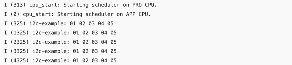
In this section, we will build and test a project using I2C driver described in the previous section. Our objective is to configure ESP32 as a Master device and read data from an I2C device. The I2C device we will be using is a nRF52 TWIS described in our previous article having slave address of 0x11 and send 5 bytes of data from 1 to 5.
Hardware
The following table describe hardware used in our project
Affiliate Disclosure: When you click on links in this section and make a purchase, this may result in this site earning a commission at no extra cost to you.
- We will use ESP32 DevKit C in our project. Checkout our previous article to see how to configure and flash a program to the kit. ESP32 is configured as I2C master device with SDA pin is pin 21, SCL pin is pin 22.
- We use nRF52 PCA10040 development kit as I2C Slave. Pin 26 and 27 of nRF52832 are used as SDA and SCL respectively.
- Connect pin 21 of ESP32 to pin 26 of nRF52
- Connect pin 22 of ESP32 to pin 27 of nRF52
Create a new project
We’ll start with the i2c_simple example in ESP-IDF which is located at esp-idf/examples/peripherals/i2c. Copy the project files to a new location.
Code
Replace code in i2c_simple_main.c by the following code
#include <stdio.h>
#include "esp_log.h"
#include "driver/i2c.h"

static const char *TAG = "i2c-example";

#define I2C_SLAVE_ADDR	0x11
#define TIMEOUT_MS		1000
#define DELAY_MS		1000

void app_main() {
	uint8_t rx_data[5];

	i2c_config_t conf = {
		.mode = I2C_MODE_MASTER,
		.sda_io_num = 21,
		.scl_io_num = 22,
		.sda_pullup_en = GPIO_PULLUP_ENABLE,
		.scl_pullup_en = GPIO_PULLUP_ENABLE,
		.master.clk_speed = 400000,
	};
	i2c_param_config(I2C_NUM_0, &conf);

	ESP_ERROR_CHECK(i2c_driver_install(I2C_NUM_0, I2C_MODE_MASTER, 0, 0, 0));

	while (1) {
		i2c_master_read_from_device(I2C_NUM_0, I2C_SLAVE_ADDR, rx_data, 5, TIMEOUT_MS/portTICK_RATE_MS);
		ESP_LOG_BUFFER_HEX(TAG, rx_data, 5);
		vTaskDelay(DELAY_MS/portTICK_RATE_MS);
	}
}
The above code configures I2C port 0 as Master, read data from I2C slave every 1 second and print out raw values. We are using ESP LOG module to dump hex values receive from the slave to the console.
Compile and flash code
To compile and flash code to ESP32, run the following commands:
get_idf
idf.py build
idf.py -p [PORT] flash
Results
Run idf.py monitor to see the log messages output from ESP32. If everything is working properly, you will see the log similar to this:
Wrapping Up
In this article, you have learnt about ESP32 I2C communication using ESP-IDF. You learnt about the APIs in i2c driver and implemented a simple project to demonstrate its usage. Thanks for reading.