· Esp32 · 3 min read
ESP32 Partition Table
The ESP32’s partition table is a critical component that defines how memory is allocated and organized in your device. In this article, we’ll explore what a partition table is, why it’s essential for managing flash storage, and how it influences your application’s behavior. You’ll learn about the different types of partitions (such as app, data, and OTA), how to create a custom partition table, and how to modify the default settings to fit your project’s needs. By the end of this guide, you’ll understand how to efficiently allocate memory in your ESP32 projects for optimal performance and flexibility.
Introduction
In this article, we will learn about ESP32 partition table: what it is, why we need partition table, how to create a partition table, how to examine a partition table of a project. Understanding partition table is important when programming ESP32.
Flash memory
Let’s have a brief review on a typically flash memory structure. A flash memory usually is organised in sectors, blocks and pages as illustrated in the below diagram
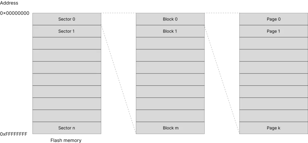
A flash memory may contains multiple sectors, each sectors may contain multiple blocks, and each blocks may have multiple pages. A page in turn consists of multiple bytes of data. A location of a byte in memory is identified by using a 32-bit address, starting from 0x00000000 to 0xFFFFFFFF.
The ESP32 DevKitC development board has an external SPI flash integrated on the module with capacity of 4 MB. Data is written to and read from the flash by using Serial Peripheral Interface protocol.
ESP32 Partition Table
A partition table is a table describing where different pieces of code or data are stored in flash memory. ESP32’s flash may contain more than 1 application, and may store different kind of data, e.g. filesystems, WiFi configurations, Bluetooth configuration etc.
The following example describes a typical partition table with a single application, no OTA (over-the-air update)
| Name | Type | Subtype | Offset | Size | Flags |
|---|---|---|---|---|---|
| nvs | data (0x01) | nvs (0x02) | 0x9000 | 24K | |
| phy_init | data (0x01) | phy (0x01) | 0xf000 | 4K | |
| factory | app (0x00) | factory (0x00) | 0x10000 | 1M |
Take a close look at this table
- You can see there are several memory regions which are defined in the table
- Each region has a name, a type, a subtype, an offset address, size and (optionally) flags
- There’s a region named nvs (non-volatile storage) which stores data resided at an address with offset 0x9000 and is 24 kB of size. nvs may be used, for example, to store wifi data.
- A region named phy_init at address offset 0xf000 and size of 4 kB to store physical layer initialisation data.
- The region contains application code is named factory and stays at address 0x10000 and has a maximum size of 1 MB.
When is the partition table used
When you are building an ESP32 project, you need to specify a partition table. Examples in ESP-IDF such as get_started, hell_world uses the built in partition table described above. You can find the csv file storing the above partition table at
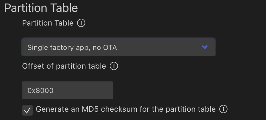
esp-idf/components/partition_table/partitions_singleapp.csvWhen building your project, ESP-IDF tools will convert this partition table from csv file to binary format and flash the partition table binary at address offset 0x8000 in flash memory.
When booting up, the second stage bootloader will read the partition table at the default address 0x8000 to find where the application is, then load and execute it.
Create a partition table
You can use one of the built-in partition tables (single factory app, no OTA or factory app, two OTA definitions) or create a custom partition table as required by your application. You can use menuconfig in Visual Studio Code to select your options
If you create a custom partition table using csv format, refer to the official documentation for the meaning of the fields and accepted values. We will revisit partition table again when we discuss about over-the-air update with ESP32 in another article.
ESP-IDF provides a python script to convert a partition table in csv format to binary format and vice versa. The python script is
esp-idf/components/partition_table/gen_esp32part.pyESP-IDF also provides another python script (parttool.py) so that on a running ESP32 target, you can read or write a partition and retrieve the partition table. This may be useful during development process.
Wrapping Up
In this article, you have learnt about partition table in ESP32. Hopefully you understand its roles in building an ESP32 project. Thanks for reading.