· Esp32 · 6 min read
ESP32 Timers with ESP-IDF
Timers are essential for managing time-based events and tasks in embedded systems, and the ESP32 provides powerful hardware timers to make this task easier. In this article, you’ll learn how to configure and control the ESP32’s hardware timers using the timer driver in ESP-IDF. We’ll explore how to set up one-shot or periodic timers, handle timer interrupts, and use timers for a variety of time-sensitive applications such as PWM generation, timeouts, or scheduled tasks. By the end of this guide, you’ll have a solid understanding of how to utilize ESP32 timers for precise control in your projects.
Introduction
In this article, we will learn about ESP32 general purpose timers. ESP32 has four 64-bit general purpose timers, which are divided into two groups, each group has two timer instances. We will learn how to initialise a timer, configure timer duration, start a timer, and how to use timer interrupt. We will implement a simple project in which a timer is used to count 1 second interval. Whenever timer expires, we will toggle a GPIO pin so that a LED connected with it blinks. Note that we will use APIs in ESP-IDF (version 4.3) to control timers.
Hardware Used
We will be using the following components to build a circuit for our project
| QTY | Component Name | Buy on amazon.com |
|---|---|---|
| 1 | ESP32 DevKit C | Amazon |
| 1 | LED Kit | Amazon |
| 1 | Resistor Kit | Amazon |
| 1 | Breadboard | Amazon |
| 1 | Jumper Wire Kit | Amazon |
Affiliate Disclosure: When you click on links in this section and make a purchase, this may result in this site earning a commission at no extra cost to you.
ESP-IDF Timer APIs
Timer library
The timer APIs are defined in driver/include/driver/timer.h and you need to include the driver before using it
#include "driver/timer.h"Initialisation
The first step when working with ESP32 timer is to initialise it. We need to use function timer_init() to specify which timer to use and what parameters to configure the timer. The function has prototype
esp_err_t timer_init(timer_group_t group_num, timer_idx_t timer_num, const timer_config_t *config);This function takes a number of arguments:
group_num: as mentioned earlier, there are two timer groups,TIMER_GROUP_0andTIMER_GROUP_1, and these are accepted value for this argument.timer_num: in each timer group, there are two timer instances,TIMER_0andTIMER_1, you need to specify which timer to use.config: a pointer that points to a timer configuration of typetimer_config_t.
This function returns ESP_OK if initialisation is successful and ESP_ERR_INVALID_ARG if there is an invalid argument.
Configure timer parameters
The timer_config_t structure contains timer settings and specifies how the timer works. It includes the following settings:
alarm_en: whether to enable (TIMER_ALARM_EN) or disable (TIMER_ALARM_DIS) timer alarm. When alarm is enabled, and an alarm value is set, the timer will generate an interrupt when its internal counter value is equal alarm value.counter_en: this value specifies whether to start timer immidately (TIMER_START) after initialisation or not (TIMER_PAUSE).counter_dir: determines to count up (TIMER_COUNT_UP) or count down (TIMER_COUNT_DOWN)auto_reload: if this value is equalTIMER_AUTORELOAD_EN, after an alarm event, the initial counter value will be reloaded and timer will start counting from the initial value. If this value is equalTIMER_AUTORELOAD_DIS, the initial counter value will not be reloaded, timer will continue to increase or decrease.divider: determines the timer frequency. By default, the timer’s clock source is typically 80 MHz, hence the timer frequency is80 MHz / divider
Set initial counter value
To set the initial counter value, you use the API timer_set_counter_value()
esp_err_t timer_set_counter_value(timer_group_t group_num, timer_idx_t timer_num, uint64_t load_val);You need to specify the timer group group_num, timer index timer_num and the value load_val to start counting from.
Set alarm value
To set alarm value, e.g. the value at which timer generates an interrupt, you use the function timer_set_alarm_value(). As before, you need to tell the function which timer group and timer number and alarm value to be set.
esp_err_t timer_set_alarm_value(timer_group_t group_num, timer_idx_t timer_num, uint64_t alarm_value);Enable timer interrupt
To enable timer interrupt, use the function timer_enable_intr()
esp_err_t timer_enable_intr(timer_group_tgroup_num, timer_idx_ttimer_num);Add timer interrupt callback
To add a timer interrupt handler, use the API timer_isr_callback_add
esp_err_t timer_isr_callback_add(timer_group_t group_num, timer_idx_t timer_num, timer_isr_t isr_handler, void *arg, int intr_alloc_flags);You need to tell which timer group and timer number are being used. The timer interrupt handler timer_isr_t has the following prototype
typedef bool (*timer_isr_t)(void *);The interrupt handler needs to return true or false. If it returns true, do task yield at the end of the ISR.
Start a timer
To start a timer, use the API timer_start() and specify which timer to run
esp_err_t timer_start(timer_group_t group_num, timer_idx_t timer_num);ESP-IDF Timer Example
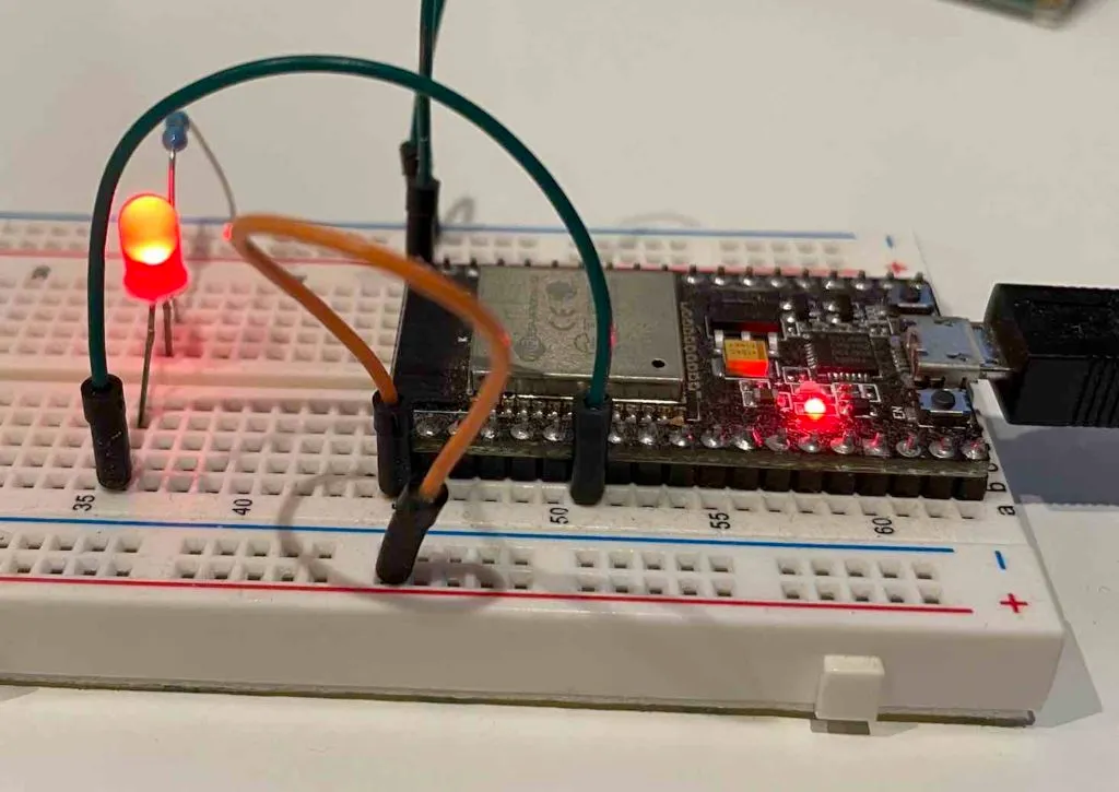
Now you have learnt about some APIs to control hardware timers of ESP32, let’s use it in practice to build a simple project: blink an LED every 1 second using a timer. The circuit includes a ESP32 DevKitC board, a resistor, a LED connected to GPIO 32 as shown in the below image:
Step 1: Create a new project
We will start by copying the timer_group example in ESP-IDF and save it to another location, for example ~/esp32projects/timer. Now run the following commands to make sure we can compile and flash the code before continuing.
get_idf
idf.py build
idf.py -p [PORT] flash
idf.py monitor
Step 2: Adding our code in app_main
After confirming everything is working, delete all code in timer_group_example_main.c by the following code
#include <stdio.h>
#include "freertos/FreeRTOS.h"
#include "freertos/task.h"
#include "freertos/semphr.h"
#include "driver/timer.h"
#include "driver/gpio.h"

#define TIMER_DIVIDER   (16)
#define LED_PIN         GPIO_NUM_32

static SemaphoreHandle_t s_timer_sem;
static bool IRAM_ATTR timer_group_isr_callback(void * args) {
    BaseType_t high_task_awoken = pdFALSE;
    xSemaphoreGiveFromISR(s_timer_sem, &high_task_awoken);
    return (high_task_awoken == pdTRUE);
}

void app_main(void)
{
    static int led_state = 0;
    gpio_set_direction(LED_PIN, GPIO_MODE_OUTPUT);
    gpio_set_level(LED_PIN, 0);
    s_timer_sem = xSemaphoreCreateBinary();
    if (s_timer_sem == NULL) {
        printf("Binary semaphore can not be created");
    }
    timer_config_t config = {
        .divider = TIMER_DIVIDER,
        .counter_dir = TIMER_COUNT_UP,
        .counter_en = TIMER_PAUSE,
        .alarm_en = TIMER_ALARM_EN,
        .auto_reload = TIMER_AUTORELOAD_EN
    };
    timer_init(TIMER_GROUP_0, TIMER_0, &config);
    timer_set_counter_value(TIMER_GROUP_0, TIMER_0, 0);
    timer_set_alarm_value(TIMER_GROUP_0, TIMER_0, (TIMER_BASE_CLK / TIMER_DIVIDER));
    timer_enable_intr(TIMER_GROUP_0, TIMER_0);
    timer_isr_callback_add(TIMER_GROUP_0, TIMER_0, timer_group_isr_callback, NULL, 0);
    timer_start(TIMER_GROUP_0, TIMER_0);
    while (1) {
        if (xSemaphoreTake(s_timer_sem, portMAX_DELAY) == pdPASS) {
            if (led_state == 0) {
                led_state = 1;
                gpio_set_level(LED_PIN, 1);
            } else {
                led_state = 0;
                gpio_set_level(LED_PIN, 0);
            }
        }
    }
}
How the code works
First, we set up timer using the APIs in the previous section. In this example, we are using TIMER_0 of TIMER_GROUP_0 to count time. We declare a variable
configto store timer configuration: count up, do not start immediately, enable alarm and auto reload. Then we calltimer_init()and pass the address ofconfigas the third parameter.In the next step, we set initial counter value to 0 and set alarm value equal to the frequency of the timer using
timer_set_counter_value()andtimer_set_alarm_value(), respectively. Note that the macroTIMER_BASE_CLKwill get us the input clock source to the timer.We then enable timer interrupt and add an interrupt handler using
timer_enable_intr()andtimer_isr_callback_add(). Finally we start the timer by callingtimer_start().We define a binary semaphore
s_timer_sem. In the timer interrupt callback, it will give the semaphore by callingxSemaphoreGiveFromISR(). This is a freeRTOS API.In the main loop, it will attempt to take the
s_timer_sem. Note that for freeRTOS, when a task is trying to take a semaphore and it is not available, it will go to Blocked state waiting for the semaphore. Once the semaphore is given by the ISR, the calling task is woken and continue execution. In this case, it will toggle the LED pinLED_PINusing GPIO APIsgpio_set_level(). You can check out our previous tutorial to learn GPIO APIs.
Build, flash and run the program
To build the program, run
idf.py buildTo flash the program, run
idf.py -p [PORT] flashAfter flashing, you should see the blue LED on the WROVER-KIT blinks every 1 second.
Wrapping Up
In this article, you have learnt about ESP32 hardware timers and how to control them using the timer driver in ESP-IDF. If you want to learn more, check out ESP32 Timer API reference here. If you have any comments, leave it in the comment section. Thanks for reading.