· Esp32 · 6 min read
ESP32 SPI Master (ESP-IDF)
The Serial Peripheral Interface (SPI) on the ESP32 is a versatile tool for high-speed communication with peripherals like displays and sensors. In this blog post, we dive into using the ESP32’s SPI peripheral as a master with the ESP-IDF framework. We’ll cover the SPI instances, explore the essential ESP-IDF APIs for SPI communication, and guide you through creating a hands-on project to control a MAX7219 module with an 8x8 LED matrix. This step-by-step tutorial equips you with the knowledge to leverage SPI for your ESP32 projects, whether you’re a beginner or an advanced developer.
Introduction
Learn how to use the ESP32 SPI peripheral with the ESP-IDF in this article. SPI instances and the APIs needed to interact with them will be covered. You will create a project that uses SPI to operate a MAX7219 module with an 8x8 LED matrix.
ESP32 SPI APIs
Initialisation
When working with ESP32 SPI, you would need to call spi_bus_initialize() first to configure SPI. This function has the following prototype
esp_err_t spi_bus_initialize(spi_host_device_t host_id, const spi_bus_config_t *bus_config, spi_dma_chan_t dma_chan);This function accepts the following arguments:
host_id: is a variable of typespi_host_device_t. This variable indicates which SPI instance is being used. There are 4 SPI instances in ESP32 (SPI0,SPI1,SPI2, andSPI3). Of those,SPI0andSPI1are reserved for accessing attached flash memory, so you should useSPI2orSPI3. You pass the valueSPI2_HOSTto tell that you are usingSPI2instance, andSPI3_HOSTif you intend to useSPI3instance.bus_configis a pointer to a constant configuration structure of typespi_bus_config_t. This variable tells which IO pins are used for MISO, MOSI, CLK and CS. For example, you can define a configuration variable like this to tell you want to use IO32 as MOSI line, IO33 as CLK line.-1means a pin is not used.max_transfer_szindicates maximum transfer in bytes.spi_bus_config_t buscfg={ .miso_io_num = -1, .mosi_io_num = 32, .sclk_io_num = 33, .quadwp_io_num = -1, .quadhd_io_num = -1, .max_transfer_sz = 32, };
dma_chanis a variable indicating which DMA channel is used. DMA or Direct Memory Access is a mechanism for SPI instance to access RAM memory directly as transfer buffer. You can select betweenSPI_DMA_DISABLED,SPI_DMA_CH1,SPI_DMA_CH2or autoSPI_DMA_CH_AUTO.
Register Slave Device
After initialising, you need to call API spi_bus_add_device() to register a slave device.
esp_err_t spi_bus_add_device(spi_host_device_t host_id, const spi_device_interface_config_t *dev_config, spi_device_handle_t *handle);This function takes a number of parameters:
host_id: it needs to know which SPI instance the slave is attaching to, so if you have usedSPI2_HOSTin the above initialisation step, you need to pass the same instance here.dev_configis a pointer to a constant configuration structure of typespi_device_interface_config_t. This variable tells information about the slave device, such as which SPI mode it is working, what is the clock speed of the slave device, etc. The following example defines a configuration variable for a slave device operate at 1 MHz clock, mode 0 and use IO25 as the chip select pin.spi_device_interface_config_t devcfg={ .clock_speed_hz = 1000000, // 1 MHz .mode = 0, //SPI mode 0 .spics_io_num = 25, // CS Pin .queue_size = 1, .flags = SPI_DEVICE_HALFDUPLEX, .pre_cb = NULL, .post_cb = NULL, };
handleis a pointer to a variable of typespi_device_handle_t. After callingspi_bus_add_device, it will return a handle, and you can use this variable to refer to the current slave device. For examplespi_device_handle_t spi2;
ESP_ERROR_CHECK(spi_bus_add_device(SPI2_HOST, &devcfg, &spi2));
Transfer data
To transfer data to SPI Slave, you can use either polling mode or interrupt mode. To transfer data using polling mode, you call spi_device_polling_transmit() API
esp_err_t spi_device_polling_transmit(spi_device_handle_t handle, spi_transaction_t *trans_desc);This function takes two arguments:
handleof typespi_device_handle_tis the variable referring to the slave device which you obtained by callingspi_bus_add_device()previously.trans_descis a pointer to a variable of typespi_transaction_tand contains description of the transaction. The following example shows how to transfer 2 bytes of data to slave.uint8_t data[2] = { 0x01, 0x02 };
spi_transaction_t t = { .tx_buffer = data, .length = 2 * 8 };
ESP_ERROR_CHECK(spi_device_polling_transmit(spi2, &t));
ESP32 SPI Sample Project
We will implement a sample project to demonstrate how to use SPI instances of ESP32. Our project is to control a 8x8 LED Matrix MAX7219 module. To control this module, you need to write data to MAX7219 registers using SPI protocol.
Hardware
The following table describes required components used in this project
| QTY | Component | Buy on Amazon |
|---|---|---|
| 1 | ESP32 DevKit C | amazon.com |
| 1 | 8x8 LED Matrix MAX7219 module | amazon.com |
| 1 | Breadboard | amazon.com |
| 1 | Jumper Wire Kit | amazon.com |
Affiliate Disclosure: When you click on links in this section and make a purchase, this may result in this site earning a commission at no extra cost to you.
Connection
Connect ESP32 Pins with MAX7219 module according to this table
| ESP32 Pin | MAX7219 Module Pin |
|---|---|
| 32 | DIN |
| 33 | CLK |
| 25 | CS |
| 3.3V | VCC |
| GND | GND |
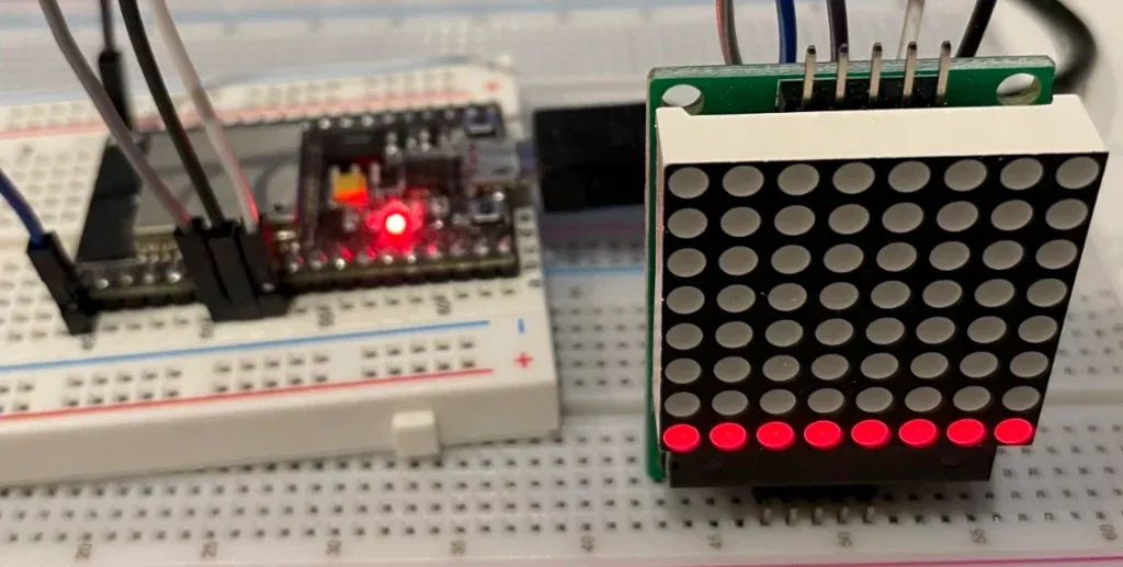
You should have a circuit look like this
Code
Code of the project is shown below
#include <stdio.h>
#include "esp_log.h"
#include "freertos/FreeRTOS.h"
#include "freertos/task.h"
#include "driver/spi_master.h"

#define CLK_PIN     33
#define MOSI_PIN    32
#define CS_PIN      25

#define DECODE_MODE_REG     0x09
#define INTENSITY_REG       0x0A
#define SCAN_LIMIT_REG      0x0B
#define SHUTDOWN_REG        0x0C
#define DISPLAY_TEST_REG    0x0F

spi_device_handle_t spi2;

static void spi_init() {
    esp_err_t ret;

    spi_bus_config_t buscfg={
        .miso_io_num = -1,
        .mosi_io_num = MOSI_PIN,
        .sclk_io_num = CLK_PIN,
        .quadwp_io_num = -1,
        .quadhd_io_num = -1,
        .max_transfer_sz = 32,
    };

    ret = spi_bus_initialize(SPI2_HOST, &buscfg, SPI_DMA_CH_AUTO);
    ESP_ERROR_CHECK(ret);

    spi_device_interface_config_t devcfg={
        .clock_speed_hz = 1000000,  // 1 MHz
        .mode = 0,                  //SPI mode 0
        .spics_io_num = CS_PIN,
        .queue_size = 1,
        .flags = SPI_DEVICE_HALFDUPLEX,
        .pre_cb = NULL,
        .post_cb = NULL,
    };

    ESP_ERROR_CHECK(spi_bus_add_device(SPI2_HOST, &devcfg, &spi2));
};

static void write_reg(uint8_t reg, uint8_t value) {
    uint8_t tx_data[2] = { reg, value };

    spi_transaction_t t = {
        .tx_buffer = tx_data,
        .length = 2 * 8
    };

    ESP_ERROR_CHECK(spi_device_polling_transmit(spi2, &t));
}

static void set_row(uint8_t row_index) {
  write_reg(row_index + 1, 0xFF);
}

static void set_col(uint8_t col_index) {
  for (int i = 0; i < 8; i++) {
    write_reg(i + 1, 0x01 << col_index);
  }
}

static void clear(void) {
  for (int i = 0; i < 8; i++) {
    write_reg(i + 1, 0x00);
  }
}

static void max7219_init() {
    write_reg(DISPLAY_TEST_REG, 0);
    write_reg(SCAN_LIMIT_REG, 7);
    write_reg(DECODE_MODE_REG, 0);
    write_reg(SHUTDOWN_REG, 1);
    clear();
}

void app_main(void)
{
    spi_init();
    max7219_init();

    while (1) {
        for (int i = 0; i < 8; i++) {
            clear();
            set_row(i);
            vTaskDelay(1000/portTICK_PERIOD_MS);
        }

        for (int i = 0; i < 8; i++) {
            clear();
            set_col(i);
            vTaskDelay(1000/portTICK_PERIOD_MS);
        }
    }
}
Full project files can be seen on Github.
Code explanation
- As described previously, you implement a function
spi_init()in which you call ESP-IDF APIsspi_bus_initialize()andspi_bus_add_device()to initialise the bus and the slave device. In this project, we are using SPI2 to control MAX7219. - You implement a function
write_reg()to write a value to a MAX7219 register. In this function, you callspi_device_polling_transmit()to initiate a blocking transfer of 2 bytes to MAX7219. - To turn on LEDs in each row and each column, you call
set_row()andset_col()respectively. These functions in turn callwrite_reg()to initiate SPI transfer to slave device. - In main loop, you simply turn on each row and then each column, then delay for 1 second using freeRTOS
vTaskDelay()API.
Wrapping Up
In this article, you have learnt how to use SPI in Master mode with ESP-IDF. You learnt about APIs to initialise, configure and transfer data to a slave device. You practice by building a project to control 8x8 LED Matrix MAX7219. To go further from here, you can check full API reference from Espressif.