· Esp32 · 6 min read
ESP32 UART with ESP-IDF
The ESP32’s Universal Asynchronous Receiver Transmitter (UART) is a powerful feature for serial communication in IoT and embedded projects. In this blog post, we explore how to effectively use UART with the ESP32 using the ESP-IDF framework. We’ll cover the ESP32’s UART hardware, delve into the ESP-IDF APIs for controlling UART modules, and provide step-by-step guidance on configuring and implementing UART communication. Whether you’re interfacing with sensors, debugging, or building complex systems, this guide will equip you with the knowledge to harness the ESP32’s UART capabilities for seamless and reliable data exchange.
Introduction
In this post, you will learn about Universal Asynchronous Receiver Transmitter (UART) with ESP32 using ESP-IDF. UART is a communication protocol found in many microcontrollers, including ESP32, due to its ease of use and requires only two wires (TX and RX). This article will explain the UART hardware in ESP32, APIs in ESP-IDF to control UARTs and steps to properly configure and use the modules. It will guide you to implement an interesting project using UART. Let’s get started.
ESP32 UART hardware
Since UART is a very common protocol, most microcontrollers (ESP32 included) have dedicated hardware blocks that supports this protocol. Using dedicated hardware helps freeup CPU resources and you normally need to configure some registers so that they can work properly. The ESP-IDF provides APIs that works with these hardware modules which we will explore in details in the next section. ESP32 has 3 UART peripherals that you can use, named UART_NUM_0, UART_NUM_1 and UART_NUM_2.
ESP-IDF UART APIs
To use ESP32 UART, you use APIs from ESP-IDF. These APIs hide the complex parts of working with UART hardware (e.g. handling reading/writing to registers) and expose easy-to-use functions. You just need to call the right APIs to configure the modules and to send/receive data. In this section, we take a look at those functions.
Configuration
When working with ESP32 UARTs, the first step is to tell which UART instance you want to use, what is baud rate, whether to use hardware flow control or parity bit, etc. Then you need to allocate resources for UART, e.g. reserving memory for transmit and receive buffers.
First, use the uart_param_config() API to set the UART parameters. This function has the following prototype:
esp_err_t uart_param_config(uart_port_t uart_num, const uart_config_t *uart_config);This function takes two arguments:
uart_numis the UART instance that you want to use. As discussed earlier, there are 3 hardware UART modules, hence you could useUART_NUM_0,UART_NUM_1andUART_NUM_2for this argument.uart_configis a pointer to a configuration structure of typeuart_config_t. The configuration structure holds UART parameters such as baud rate, data bits, etc.
The following example shows you how to initialise UART1 instance with a baud rate of 115200, 8 bit data, no parity, no flow control
uart_config_t uart1_config = {
    .baud_rate = 115200,
    .data_bits = UART_DATA_8_BITS,
    .parity = UART_PARITY_DISABLE,
    .stop_bits = UART_STOP_BITS_1,
    .flow_ctrl = UART_HW_FLOWCTRL_DISABLE,
};

ESP_ERROR_CHECK(uart_param_config(UART_NUM_1, &uart1_config));
Next step is to set the pins for UART communication, e.g. which pin is RX pin and which pin is TX pin. You use the API uart_set_pin() to do this job.
esp_err_t uart_set_pin(uart_port_t uart_num, int tx_io_num, int rx_io_num, int rts_io_num, int cts_io_num);You can specify which pins to be used as RX and TX which is quite flexible. Note that on ESP32 there are some dedicated pins used as input pins which you should not be using for TX pins. Refer to the datasheet of ESP32 for more information. The following example shows how to set pin 23 as TX pin and pin 22 as RX pin.
ESP_ERROR_CHECK(uart_set_pin(UART_NUM_1, 23, 22, 0, 0));Initialisation
After specifying parameters for UART instance being used, you need to allocate necessary resources by calling uart_driver_install():
esp_err_t uart_driver_install(uart_port_t uart_num, int rx_buffer_size, int tx_buffer_size, int queue_size, QueueHandle_t *uart_queue, int intr_alloc_flags)For example, you could use the API as follow
ESP_ERROR_CHECK(uart_driver_install(UART_NUM_1, 1024, 1024, 0, NULL, 0));Transmitting data
To transmit data to UART, you use the function uart_write_bytes() and pass in the UART instance being used, a pointer to the transmitting buffer and length
int uart_write_bytes(uart_port_t uart_num, const void *src, size_t size)Receiving data
To receive data from UART, use the API uart_read_bytes()
int uart_read_bytes(uart_port_t uart_num, void *buf, uint32_t length, TickType_t ticks_to_wait)This function accepts the UART instance as the first argument, then a pointer to the receive buffer, the data length and a parameter to specify how long it should wait to receive data. If there’s an error during receiving data, this function returns with an error code of -1, otherwise it returns the number of data bytes it received.
ESP-IDF UART Example
In this section, we will take a look at a practical project to understand how to use ESP32 UART.
Hardware
You will need the following hardware components for this project
- An ESP32 development kit. We will be using ESP32-DevKitC in this project.
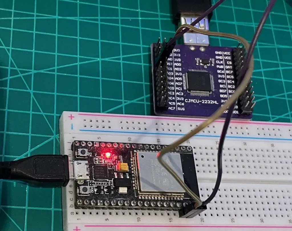
- A UART-to-USB dongle. We will use CJMCU-2232HL module which features dual channel UART-to-USB bridge. This module will convert UART to USB signal so that we can receive and display UART signal on a computer
Schematic
- We will use ESP32 pin 23 as TX pin and pin 22 as RX pin
- Connect ESP32 pin 23 and CJMCU-2232HL pin ADBUS1, this is RX pin channel A of the module
- Connect ESP32 pin 22 and CJMCU-2232HL pin ADBUS0, this is TX pin channel A of the module.
The image below shows the connection
Software
- ESP-IDF. You should have ESP-IDF installed on your computer
- VSCode extension for ESP-IDF.
- VCP Driver to enable communication between a host computer and CJMCU-2232HL module.
Create new project
Now with necessary hardware and software components ready, let’s create a new ESP32 project with VSCode extension for ESP-IDF.
Adding code
Add the following code to your main.c file
#include <stdio.h>
#include "freertos/FreeRTOS.h"
#include "freertos/task.h"
#include "driver/uart.h"
#include "driver/gpio.h"

static void uart_task(void *arg)
{
    uart_config_t uart1_config = {
        .baud_rate = 115200,
        .data_bits = UART_DATA_8_BITS,
        .parity    = UART_PARITY_DISABLE,
        .stop_bits = UART_STOP_BITS_1,
        .flow_ctrl = UART_HW_FLOWCTRL_DISABLE,
    };

    ESP_ERROR_CHECK(uart_param_config(UART_NUM_1, &uart1_config));
    ESP_ERROR_CHECK(uart_set_pin(UART_NUM_1, 23, 22, 0, 0));
    ESP_ERROR_CHECK(uart_driver_install(UART_NUM_1, 1024, 1024, 0, NULL, 0));

    uint8_t *data = (uint8_t *) malloc(1024);

    while (1) {
        int len = uart_read_bytes(UART_NUM_1, data, (1024 - 1), 20 / portTICK_PERIOD_MS);
        uart_write_bytes(UART_NUM_1, (const char *) data, len);
    }
}

void app_main(void)
{
    xTaskCreate(uart_task, "uart_task", 4096, NULL, 10, NULL);
}
How to code works
In this project, we create a freeRTOS task named uart_task by using freeRTOS xTaskCreate() API. In this task, we initialise UART1 instance and use it to transmit data and receive data from UART1. As you can see, we use the APIs described in previous sections, including uart_param_config(), uart_set_pin() and uart_driver_install(). In the main task loop, it just waits for data sent from a computer, then send back the data it receives.
Testing the code
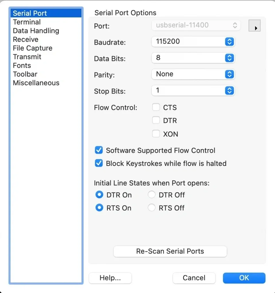
Now build, flash and run the code. Connect the UART-to-USB bridge to a computer and fire up a UART terminal. You can use a terminal like CoolTerm to send and receive data via UART. Configure the UART terminal in Coolterm like this, which matches with the configuration in your ESP32 code.
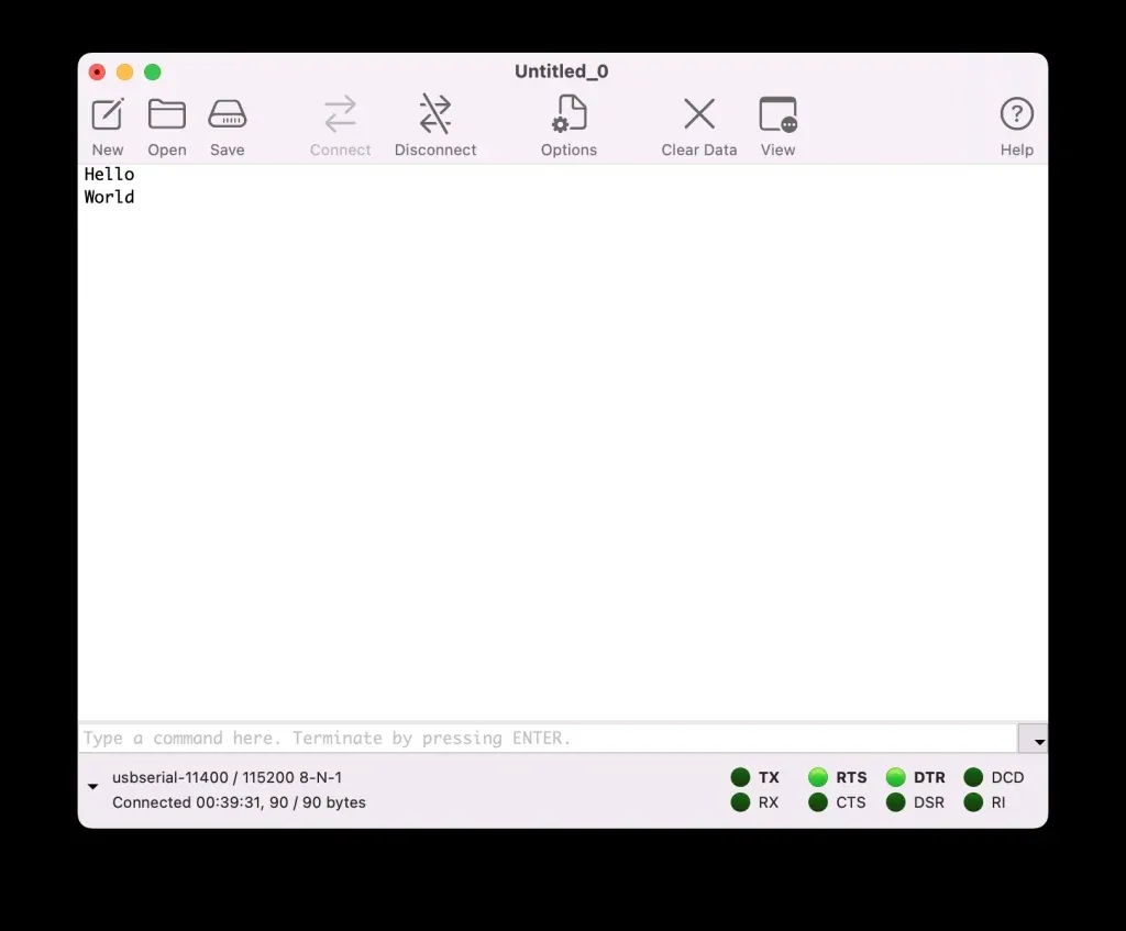
Now enter some words in Coolterm, you will see that the exact same words displayed on the screen.
Wrapping Up
In this post, you have seen how to work with UART instances in ESP32 using ESP-IDF APIs. You have implemented a practical project to understand how things work. To go futher from here, you can take a look at full API reference from Espressif here. Thanks for reading.