· Esp32 · 7 min read
ESP32 PWM using LEDC peripheral (ESP-IDF)
The LED Control (LEDC) peripheral on the ESP32 is a powerful tool for generating Pulse Width Modulation (PWM) signals, ideal for applications like LED dimming and motor control. In this blog post, we explore the capabilities of the LEDC peripheral and the ESP-IDF APIs used to configure it. You’ll learn how to create a hands-on project that uses PWM to control the color of an RGB LED, with step-by-step instructions. Whether you’re a beginner or an experienced developer, this guide will help you master PWM on the ESP32 for dynamic and colorful projects.
Introduction
This article will teach you how to produce PWM signals using the ESP32 LEDC peripheral. You will become familiar with the LEDC capabilities and APIs before creating a project in which the ESP32 controls the RGB LED’s colour. You may instruct the ESP32 to display any colour you like by adjusting the intensity of the red, green, and blue LEDs.
ESP32 LEDC Peripheral
Channels
The ESP32 LEDC peripheral is capable of producing PWM signals. It has 16 channels which are divided in two groups, each group has 8 channels. One group operates in high speed mode and the other group works in low speed mode. Depending on your application, you can choose one mode or the other.
High and Low speed mode
- In high speed mode, the PWM duty cycle is updated automatically using hardware without CPU involvement. This is useful in some applications, for example, when changing LED intensity gradually. When operating in high speed mode, you just need to do initial setup.
- In low speed mode, PWM duty cycle is modified by using software, i.e. using CPU resources. You explicitly call LEDC APIs to update its duty cycle.
LEDC parameters
There are several parameters that you need to consider when generating a PWM signal using LEDC peripheral:
- Channel: which channel are you using. As discussed above, there are 16 channels, from 0 to 15.
- GPIO pin number: which IO pin is used to drive output signal. You can choose any available IO pins which is quite flexible
- PWM Frequency: this is the frequency of the PWM signal which is dependant on the clock source.
- Clock source: you can configure LEDC to use one of the following clock sources: ABP_CLK (80 MHz), REF_TICK (1 MHz), RTC8M_CLK (8 MHz).
- Duty cycle: this is the parameter that determine how long the signal is high during an interval. A duty cycle of 50% means it is high half of the interval and low during the other half. A duty cycle of 10% means the signal is high 10% of a PWM interval.
- Duty cycle resolution: Each interval is divided in
2^(duty_resolution) - 1equal spaces. The duty cycle resolution determines the minimum on time that can be set during 1 interval. For example, if duty cycle resolution is 13 bit, the total spaces in each interval is8192 - 1. To achieve a duty cycle of 50%, you need to setdutyvalue to50% * (8192 - 1) = 4095. - Timer: LEDC has 3 timer modules (
LEDC_TIMER_0,LEDC_TIMER_1andLEDC_TIMER_2) that you can choose.
ESP32 LEDC APIs
Let’s take a look at the LEDC APIs in ESP-IDF in this section.
Configure LEDC Timer
To configure a LEDC timer, you use the API ledc_timer_config()
esp_err_t ledc_timer_config(const ledc_timer_config_t *timer_conf);This function takes an argument which is a pointer to a configuration structure variable of type ledc_timer_config_t. This structure determines which mode to use (high or low speed), which timer to use, duty resolution, PWM frequency and clock source). The following example configures a LEDC_TIMER_0 in low speed mode, 13 bit duty resolution and output frequency of 1 kHz.
ledc_timer_config_t ledc_timer = {
    .speed_mode       = LEDC_LOW_SPEED_MODE,
    .timer_num        = LEDC_TIMER_0,
    .duty_resolution  = LEDC_TIMER_13_BIT,
    .freq_hz          = 1000,
    .clk_cfg          = LEDC_AUTO_CLK
};
ESP_ERROR_CHECK(ledc_timer_config(&ledc_timer));
Configure LEDC channel
To configure a LEDC channel, use the API ledc_channel_config()
esp_err_t ledc_channel_config(const ledc_channel_config_t *ledc_conf);This function accepts a pointer to a configuration structure of type ledc_channel_config_t. You can specify which channel to use, which IO pin to drive output signal, high or low speed, whether to use interrupt. For example, to use channel 0 and IO pin 32 in low speed mode:
ledc_channel_config_t ledc_channel = {
    .speed_mode     = LEDC_LOW_SPEED_MODE,
    .channel        = LEDC_CHANNEL_0,
    .timer_sel      = LEDC_TIMER_0,
    .intr_type      = LEDC_INTR_DISABLE,
    .gpio_num       = 32,
    .duty           = 0,
    .hpoint         = 0
};
ESP_ERROR_CHECK(ledc_channel_config(&ledc_channel));
Set and update duty cycle
To set and update PWM duty cycle, you use APIs ledc_set_duty() and ledc_update_duty(), respectively
esp_err_t ledc_set_duty(ledc_mode_t speed_mode, ledc_channel_t channel, uint32_t duty);
esp_err_t ledc_update_duty(ledc_mode_t speed_mode, ledc_channel_t channel);
Full API reference can be found in Espressif documentation.
ESP32 PWM Project Example
Now you have learnt about the LEDC peripheral and its APIs, let’s build an application to control the color of a RGB LED. Our objective is to output any color by specifying the RGB color code.
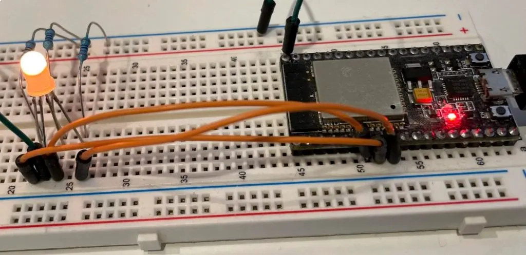
Hardware used
| QTY | Component Name | Buy on amazon.com |
|---|---|---|
| 1 | ESP32 DevKit C | Amazon |
| 1 | RGB LED | Amazon |
| 1 | Resistor Kit | Amazon |
| 1 | Breadboard | Amazon |
| 1 | Jumper Wire Kit | Amazon |
Affiliate Disclosure: When you click on links in this section and make a purchase, this may result in this site earning a commission at no extra cost to you.
Schematic
You will connect 3 IO pins of ESP32 development kit to control 3 pins of RGB LED following this table:
| ESP32 IO Pin | RGB Pin |
|---|---|
| 32 | Red |
| 33 | Green |
| 25 | Blue |
| GND | Ground |
Code
#include <stdio.h>
#include "driver/ledc.h"
#include "esp_err.h"
#include "freertos/FreeRTOS.h"
#include "freertos/task.h"

typedef struct {
    uint8_t r;
    uint8_t g;
    uint8_t b;
} color_t;

#define LED_RED_PIN         33
#define LED_GREEN_PIN       32
#define LED_BLUE_PIN        25

ledc_timer_config_t ledc_timer = {
    .speed_mode = LEDC_LOW_SPEED_MODE,
    .timer_num  = LEDC_TIMER_0,
    .duty_resolution = LEDC_TIMER_13_BIT,
    .freq_hz = 1000,
    .clk_cfg = LEDC_AUTO_CLK
};

ledc_channel_config_t ledc_channel[3];

static void init(void)
{
    ESP_ERROR_CHECK(ledc_timer_config(&ledc_timer));

    ledc_channel[0].channel = LEDC_CHANNEL_0;
    ledc_channel[0].gpio_num = LED_RED_PIN;

    ledc_channel[1].channel = LEDC_CHANNEL_1;
    ledc_channel[1].gpio_num = LED_GREEN_PIN;

    ledc_channel[2].channel = LEDC_CHANNEL_2;
    ledc_channel[2].gpio_num = LED_BLUE_PIN;

    for (int i = 0; i < 3; i++)
    {
        ledc_channel[i].speed_mode = LEDC_LOW_SPEED_MODE;
        ledc_channel[i].timer_sel = LEDC_TIMER_0;
        ledc_channel[i].intr_type = LEDC_INTR_DISABLE;
        ledc_channel[i].duty = 0;
        ledc_channel[i].hpoint = 0;

        ESP_ERROR_CHECK(ledc_channel_config(&ledc_channel[i]));
    }
}

static void setColor(color_t color)
{
    uint32_t red_duty = 8191 * color.r / 255;
    uint32_t green_duty = 8191 * color.g / 255;
    uint32_t blue_duty = 8191 * color.b / 255;

    ESP_ERROR_CHECK(ledc_set_duty(LEDC_LOW_SPEED_MODE, LEDC_CHANNEL_0, red_duty));
    ESP_ERROR_CHECK(ledc_update_duty(LEDC_LOW_SPEED_MODE, LEDC_CHANNEL_0));

    ESP_ERROR_CHECK(ledc_set_duty(LEDC_LOW_SPEED_MODE, LEDC_CHANNEL_1, green_duty));
    ESP_ERROR_CHECK(ledc_update_duty(LEDC_LOW_SPEED_MODE, LEDC_CHANNEL_1));

    ESP_ERROR_CHECK(ledc_set_duty(LEDC_LOW_SPEED_MODE, LEDC_CHANNEL_2, blue_duty));
    ESP_ERROR_CHECK(ledc_update_duty(LEDC_LOW_SPEED_MODE, LEDC_CHANNEL_2));
}

void app_main(void)
{
    const color_t red = { .r = 255, .g = 0, .b = 0 };
    const color_t green = { .r = 0, .g = 255, .b = 0 };
    const color_t blue = { .r = 0, .g = 0, .b = 255 };
    const color_t yellow = { .r = 255, .g = 255, .b = 0 };
    const color_t purple = { .r = 128, .g = 0, .b = 128 };
    const color_t silver = { .r = 192, .g = 192, .b = 192 };

    color_t sample_colors[6] = { red, green, blue, yellow, purple, silver };

    init();

    while (1) {
        for (int i = 0; i < 6; i++)
        {
            printf("Color %d\r\n", i);
            setColor(sample_colors[i]);
            vTaskDelay(pdMS_TO_TICKS(2000));
        }
    }
}
Full code project can be seen on Github.
Code explanation
- In the above code, you have configured to use
LEDC_TIMER_0using the APIledc_timer_config(). You pass the address of a configuration variableledc_timerwhich tells to use 13 bit duty resolution, 1 kHz output frequency and in low speed mode. - You use 3 LEDC channels,
LEDC_CHANNEL_0,LEDC_CHANNEL_1andLEDC_CHANNEL_2to drive Red, Green and Blue LEDs respectively. Channel configurations are stored in an arrayledc_channel[3]and passed in APIledc_channel_config()in a loop, each loop configures a channel. - You define a structure
color_twhich specifies the red, green and blue component of a color. - To show a color, you call
setColor()function. Inside this function, you set and update duty cycle for each LEDC channel based on the value of the red, green or blue component, for example, thered_dutyvalue is calculated by8191 * color.r / 255. This is because duty resolution is set to 13 bit. - In the main
whileloop, you iterate through an array of pre-defined colors and displays them, then idle for 2 seconds.
Wrapping Up
In this article, you have learnt about PWM generation using ESP32 LEDC module and ESP-IDF. In the next article, you will further develop from this project to build smart lighting application.