· Esp32 · 8 min read
Controlling RGB LEDs using ESP32 Component (ESP-IDF)
In this guide, we’ll show you how to control RGB LEDs using the ESP32 by building a custom component in the ESP-IDF framework. By structuring your code into reusable components, you can make your projects more modular and maintainable. You’ll learn how to create an RGB LED control component, configure it for different colors and brightness levels, and integrate it into your larger ESP32 applications. This approach will allow you to easily manage your code, scale your projects, and enhance the reusability of your components across different applications.
Introduction
In this article, you will learn how to use ESP32 to control RGB LEDs using Espressif official development framework ESP-IDF. It is trivial to turn on or off a LED. All you need to do is to configure a pin as an output port, then set or clear the pin to make the LED light up or shutdown, depending on the LED is active low or high. In this guide, instead of calling ESP-IDF APIs directly to control the input/output ports, we will be building a RGB component that can be configured and re-used in different projects. Let’s see how it can be done.
Hardware Used
In this article, we will be using the following hardware
| QTY | Component Name | Buy on amazon.com |
|---|---|---|
| 1 | ESP32 WROVER KIT | Amazon |
Affiliate Disclosure: When you click on links in this section and make a purchase, this may result in this site earning a commission at no extra cost to you.
RGB LEDs
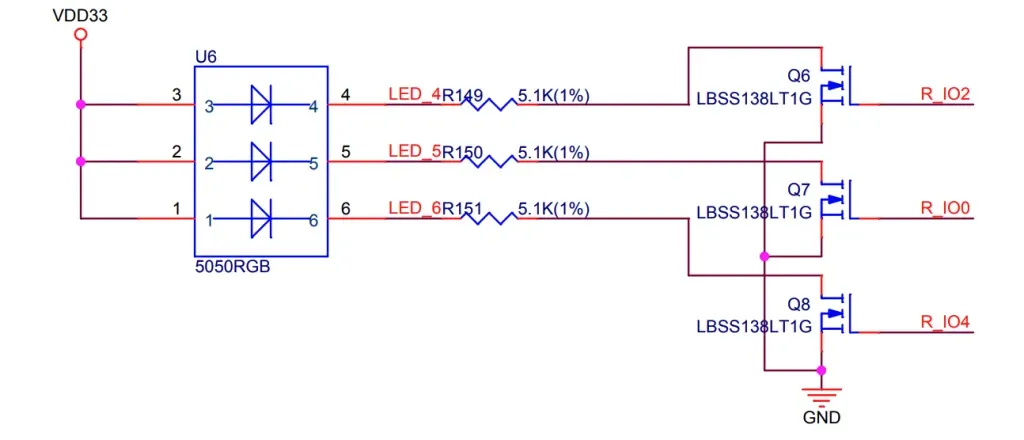
Before building a RGB component, you need to understand the hardware first. A RGB LED consists of 3 LEDs (Light Emitting Diodes) with 3 colors: Red (R), Green (G) and Blue (B). These lights can be turned on or off invidually. Depending on the circuit connection, a LED may be turned on by writing 1 to the ESP32 pin that control it. In this case, the LED is said to be active high. It may also be turned on by setting the ESP32 pin low, in which case it is said to be active low.
Below is an circuit diagram of a RGB LED that is connected to GPIO0, GPIO2 and GPIO4 of ESP32 on ESP32-WROVER-KIT. As you can see, the LEDs are active high in this case, as if you set the GPIO pins high, there is a current path from supply rail go through the LEDs and to ground. If you set the pins low, this path is disconnected and the LEDs will be turned off.
Building RGB Component
You can create custom components as part of your esp32 IDF project. The benefit of using components is you can re-use it by just copying it over to your new project. You can also specify configuration parameters, so that you don’t need to hard-coded your pins, for example. Creating a component is similar to building a library that you can use multiple times in different projects.
Create component files
To create a RGB component, you will need to create a folder named rgb inside the components folder of your project. You will then need to add a number of files according to the below figure.
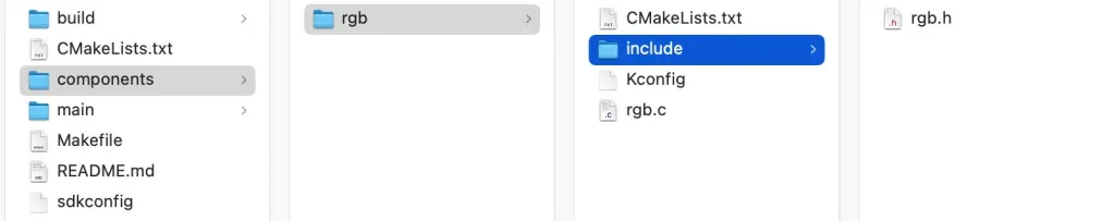
As can be from the figure, a component has the following files:
CMakeLists.txt: In this file, you need to register the component by addingidf_component_register(SRCS “rgb.c” INCLUDE_DIRS “include”)
This line tells the build system that you want to register a component with source file rgb.c and the header resides in the include folder. When compiling the project, the build tools will look for these files and compile them.
KConfig: This file contains the parameters of the components. For example, you can define which pin connects to RED LED, which pin connects to GREEN LED and which pin connects to BLUE LED. By putting parameters in KConfig file, you don’t need to hard code your pins and it makes it easier to bring the component to another project.rgb.c: the source file containing component implementation.include/rgb.h: the header file which expose component APIs to outside world.
If you are using VSCode, there’s a command to do exactly the same thing graphically. You need to run the command ESP-IDF: Create new ESP-IDF Component
Defining component configuration
To make a component modular and reusable, let’s try to identify which parameters we can use as configuration. A component configuration is defined in a file named ‘Kconfig’. The configuration starts with menu followed by a meaningful name and it ends with endmenu. You will add choices and selections between these two lines.
menu "RGB Configuration"

endmenu
Now let’s add a configuration option to tell which pin is used to control RED LED. Add the following texts in between menu and endmenu
menu "RGB Configuration"

    config RED_LED_PIN
        int "RED GPIO Pin Number"
        range 0 48
        default 0
        help
            GPIO Pin Number to control RED LED

endmenu
Here you add a configuration by using config keyword, followed by the name RED_LED_PIN. It accepts an integer number between 0 and 48 and if you leave it blank, it will use the default value of 0. You can also add text in the help section to explain the meaning of this configuration to make it easier for other people to understand your component.
You might also want to add other configurations for choosing which pins to control GREEN and BLUE LEDs as well.
    config GREEN_LED_PIN
        int "GREEN GPIO Pin Number"
        range 0 48
        default 2
        help
            GPIO Pin Number to control GREEN LED

    config BLUE_LED_PIN
        int "BLUE GPIO Pin Number"
        range 0 48
        default 4
        help
            GPIO Pin Number to control BLUE LED
To select between active low and active high, you can create a configuration like this
    choice LED_POLARITY
        prompt "Choose LED polarity"
        default LED_ACTIVE_HIGH
        help
            Specify if LEDs are active low or active high

        config LED_ACTIVE_HIGH
            bool "ACTIVE HIGH"
        config LED_ACTIVE_LOW
            bool "ACTIVE LOW"
    endchoice
If you are using Visual Studio Code, you can see the configuration by running command ESP-IDF: SDK Configuration editor (menuconfig). It will open up a window in which you can see your definitions.
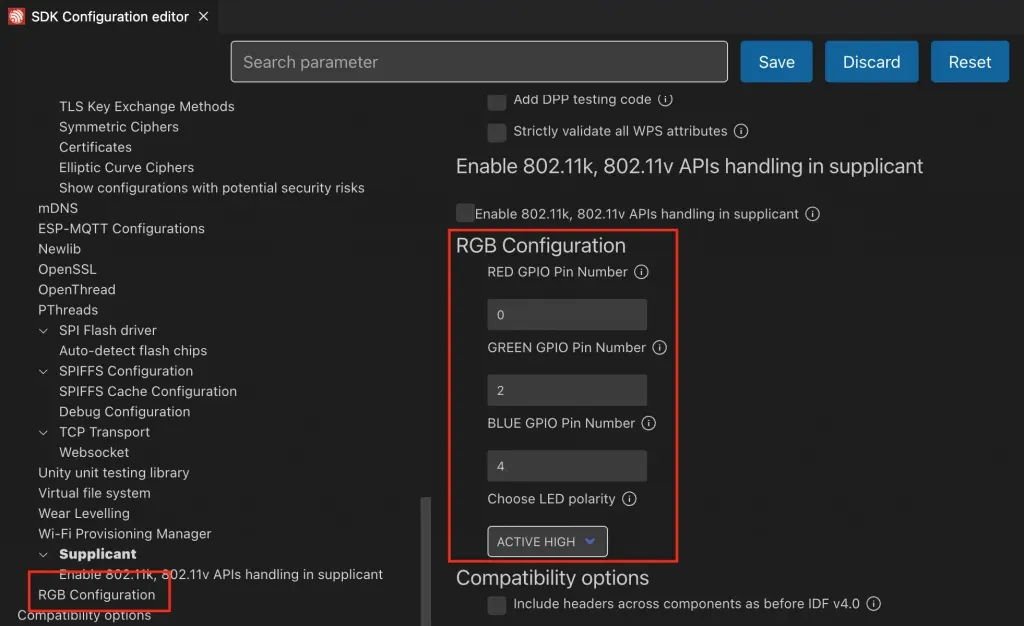
You can also see that the following lines are automatically generated in sdkconfig file
#
# RGB Configuration
#
CONFIG_RED_LED_PIN=0
CONFIG_GREEN_LED_PIN=2
CONFIG_BLUE_LED_PIN=4
CONFIG_LED_ACTIVE_HIGH=y
# CONFIG_LED_ACTIVE_LOW is not set
# end of RGB Configuration
# end of Component config
Implementing RGB component
Add the following code to rgb.h
#pragma once

typedef enum {
    RGB_RED,
    RGB_GREEN,
    RGB_BLUE
} rgb_led_t;

typedef enum {
    RGB_ON,
    RGB_OFF
} rgb_state_t;

void rgb_init();
void rgb_ctrl(rgb_led_t led, rgb_state_t state);
In this header file, you simply define an enumeration rgb_led_t so that you can refer to specific LED in your code. You also define another enumeration rgb_state_t which tells if the LED is on or off. The component includes two functions: rgb_init() and rgb_ctrl(). The rgb_init() function is to initialise the I/O pins that control the LEDs as digital output port. The rgb_ctrl() function will turn a led on or off.
Now add the following code to rgb.c
#include <stdio.h>
#include "rgb.h"
#include "driver/gpio.h"

#define RED_PIN     CONFIG_RED_LED_PIN
#define GREEN_PIN   CONFIG_GREEN_LED_PIN
#define BLUE_PIN    CONFIG_BLUE_LED_PIN

void rgb_init()
{
    gpio_set_direction(RED_PIN, GPIO_MODE_OUTPUT);
    gpio_set_direction(GREEN_PIN, GPIO_MODE_OUTPUT);
    gpio_set_direction(BLUE_PIN, GPIO_MODE_OUTPUT);
}

void rgb_ctrl(rgb_led_t led, rgb_state_t state)
{
#ifdef CONFIG_LED_ACTIVE_HIGH
    if (led == RGB_RED)
        gpio_set_level(RED_PIN, (state == RGB_ON) ? 1 : 0);

    if (led == RGB_GREEN)
        gpio_set_level(GREEN_PIN, (state == RGB_ON) ? 1 : 0);

    if (led == RGB_BLUE)
        gpio_set_level(BLUE_PIN, (state == RGB_ON) ? 1 : 0);

#endif

#ifdef CONFIG_LED_ACTIVE_LOW
    if (led == RGB_RED)
        gpio_set_level(RED_PIN, (state == RGB_ON) ? 0 : 1);

    if (led == RGB_GREEN)
        gpio_set_level(GREEN_PIN, (state == RGB_ON) ? 0 : 1);

    if (led == RGB_BLUE)
        gpio_set_level(BLUE_PIN, (state == RGB_ON) ? 0 : 1);
#endif
There are a few things to note in this component implementation:
- We add
#define RED_PIN CONFIG_RED_LED_PIN. Take a look back at theKConfigfile where you add a config namedRED_LED_PINas an integer number from 0 to 48. When you runmenuconfig, a definitionCONFIG_RED_LED_PIN=0is automatically added to thesdkconfigfile. This file is included during compiling process, hence the#define RED_PIN CONFIG_RED_LED_PINis equivalent to#define RED_PIN 0and is valid. - We used
gpio_set_direction()API in ESP-IDFdriver/gpio.hto configure a pin as digital output port. - We used the
gpio_set_level()API in ESP-IDF to control the digital output of an I/O pin. - We used directive
#ifdef CONFIG_LED_ACTIVE_HIGH ... #endifto tell the compiler to compile this section of code only ifCONFIG_LED_ACTIVE_HIGHexists.
Using RGB component
We will implement a project using RGB component that we created previously. Create a new project in VSCode from the bare template
Now create a folder named components in the project folder and copy our component rgb to that folder. Add the following code to app_main() function of main.c:
#include <stdio.h>
#include "rgb.h"
#include "freertos/FreeRTOS.h"
#include "freertos/task.h"

void app_main(void)
{
    rgb_init();

    while (1)
    {
        rgb_ctrl(RGB_RED, RGB_ON);
        rgb_ctrl(RGB_BLUE, RGB_OFF);
        rgb_ctrl(RGB_GREEN, RGB_OFF);

        vTaskDelay(pdMS_TO_TICKS(1000));

        rgb_ctrl(RGB_RED, RGB_OFF);
        rgb_ctrl(RGB_BLUE, RGB_ON);
        rgb_ctrl(RGB_GREEN, RGB_OFF);

        vTaskDelay(pdMS_TO_TICKS(1000));

        rgb_ctrl(RGB_RED, RGB_OFF);
        rgb_ctrl(RGB_BLUE, RGB_OFF);
        rgb_ctrl(RGB_GREEN, RGB_ON);

        vTaskDelay(pdMS_TO_TICKS(1000));
    }
}
In this project, we simply call rgb_init() to initialise the RGB LED, and use rgb_ctrl() to sequentially turn on RED, BLUE, and GREEN LEDs every 1 second. You can see that by using component, we do not need to interact with ESP-IDF APIs directly, and there is no hard-coded value in our code. The result of the above code can be seen in this video
Wrapping Up
In this article, you have learnt how to build a RGB component in ESP-IDF to control a RGB LED. It is recommended to build components in your ESP-IDF project to increase reusability and make your project easier to manage.
Where to go from here
If you want to dive deeper, ESP-IDF build system is explained in great detail in ESP32’s official documentation. It may take quite a bit of time to read and fully understand the document.