· Esp32 · 6 min read
Control LEDs using ESP32 Web Server (ESP-IDF)
The ESP32 is a powerful microcontroller that can be easily integrated into IoT projects. In this tutorial, you’ll learn how to create an ESP32 application using the ESP-IDF framework to control LEDs via an HTTP web server. We’ll guide you through the process of setting up the ESP32 web server, creating endpoints to control the LEDs, and connecting the ESP32 to your Wi-Fi network. With clear examples and practical code, you’ll be able to build a responsive web interface to toggle LEDs, providing a simple and effective way to control hardware remotely over the network.
Introduction
You will learn how to create an ESP32 application utilising the ESP-IDF framework to control LEDs using an HTTP web server in this tutorial. Stations can connect to the WiFi network that the ESP32 creates and access the web server. By sending HTTP requests to the server, station devices can obtain the LED status and set LED states.
Project Objectives
By going through this project, you will learn:
- Build a web server to control LEDs (view, turn on, off) remotely through a local WiFi network
- Handle HTTP requests and serve HTML documents to clients using ESP-IDF
Required components
This project uses the following components
| QTY | Component Name | Buy on amazon.com |
|---|---|---|
| 1 | ESP32 DevKit C | Amazon |
| 1 | LED Kit | Amazon |
| 1 | Resistor Kit | Amazon |
| 1 | Breadboard | Amazon |
| 1 | Jumper Wires | Amazon |
Affiliate Disclosure: When you click on links in this section and make a purchase, this may result in this site earning a commission at no extra cost to you.
Schematic
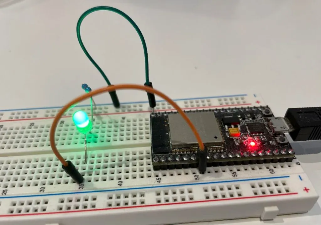
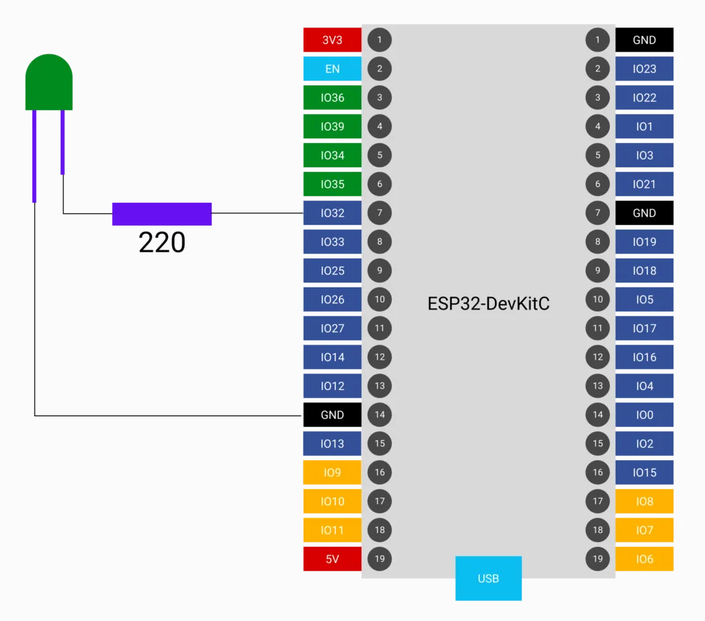
Connect the circuit as shown in the below diagram. Refer to our previous article to understand pinouts of ESP32 DevKit C development board. You will use one of available IO pins to drive a LED, for example GPIO32 (or pin 7 from the top on the left hand side of the kit). In this configuration, LED is active high, which means setting GPIO32 high will turn the LED on and clearing GPIO32 will turn the LED off.
Analysis
There are several tasks that you need to do in this project. Let’s have an overview of different components of your program:
- You must open up access to your web server so that clients can send http queries. You can set up the ESP32 to function as a WiFi access point, allowing clients to search for it and connect to it using established network parameters. In our previous lesson, we covered the process of setting up the ESP32 as a WiFi AP.
- Build a web server that responses to http requests from clients. A web server receives http requests, takes some actions and returns messages back to station devices. In this project, you will send back a html document which can be displayed on station’s web browser. You have already seen a simple http web server in our previous article, and in this project, you will extend the functionality of this server.
- When a client wants to get a LED’s state (whether it is on or off), it sends a http request with the following format
http://esp32_ip_address/. You will implement a uri handler to process this request, in which it will read LED state, then send back a html document containing a<h3>tag indicating LED status, and two anchor tags<a>which are shown as Turn ON and Turn OFF buttons. - When you click Turn ON button, a http request is sent to the server in the format
http://esp32_ip_address/on. You will implement a uri handler to setGPIO32to high so that LED is on, then send back a html document indicating LED has been turned on successully. - Similarly, if you click Turn OFF button, a GET request
http://esp32_ip_address/offis sent to the server to turn the LED off. A html document is sent back to the client and shown in station’s browser indicating LED has been turn off.
Code and explanation
Source code of the project can be seen on Github. This section explains the important parts of the code.
Setting up WiFi
As mentioned above, the first step is to set up ESP32 as an AP. This is done by calling the function setup_wifi(). This function performs all the necessary steps to initialise and configure WiFi as explained in detail previously. This includes creating different tasks such as WiFi driver task, TCP/IP task, event task, perform binding of TCP/IP stack and esp_netif, etc.
setup_wifi();Create a web server
Next step is to create a web server by calling setup_server() function. A web server is created using API from ESP-IDF httpd components. Different steps required when working with web server are covered in our previous article.
setup_server();Handle http requests
There are 3 handlers that you need to implement: /, /on and /off. Hence in your code, you define 3 variables of type http_uri_t
httpd_uri_t uri_get = {
    .uri      = "/",
    .method   = HTTP_GET,
    .handler  = get_handler,
    .user_ctx = NULL
};

httpd_uri_t uri_on = {
    .uri      = "/on",
    .method   = HTTP_GET,
    .handler  = on_handler,
    .user_ctx = NULL
};

httpd_uri_t uri_off = {
    .uri      = "/off",
    .method   = HTTP_GET,
    .handler  = off_handler,
    .user_ctx = NULL
};
You register these handlers in setup_server() by using httpd_register_uri_handler() API, so that when the server receives these requests, it will call respective handler.
httpd_register_uri_handler(server, &uri_get);
httpd_register_uri_handler(server, &uri_on);
httpd_register_uri_handler(server, &uri_off);
In the handler, ESP32 will control LED state and returns a HTML document. For example, in on_handler, LED is turned on by using API gpio_set_level(). A HTML document is an array of characters containing HTML tags and is sent back by using httpd_resp_send() API.
esp_err_t on_handler(httpd_req_t *req)
{
    gpio_set_level(LED_PIN, 1);
    led_state = 1;
    const char resp[] = "<h3>LED State: ON</h3><a href=\"/on\"><button>Turn ON</button></a><a href=\"/off\"><button>Turn OFF</button</a>";
    httpd_resp_send(req, resp, HTTPD_RESP_USE_STRLEN);
    return ESP_OK;
}
Setting network credentials
Now before compiling your code, you need to set your network credentials. In this project, you have used component configuration which allows you to not use hard-coded values in your code. Run idf.py menuconfig to open project configuration
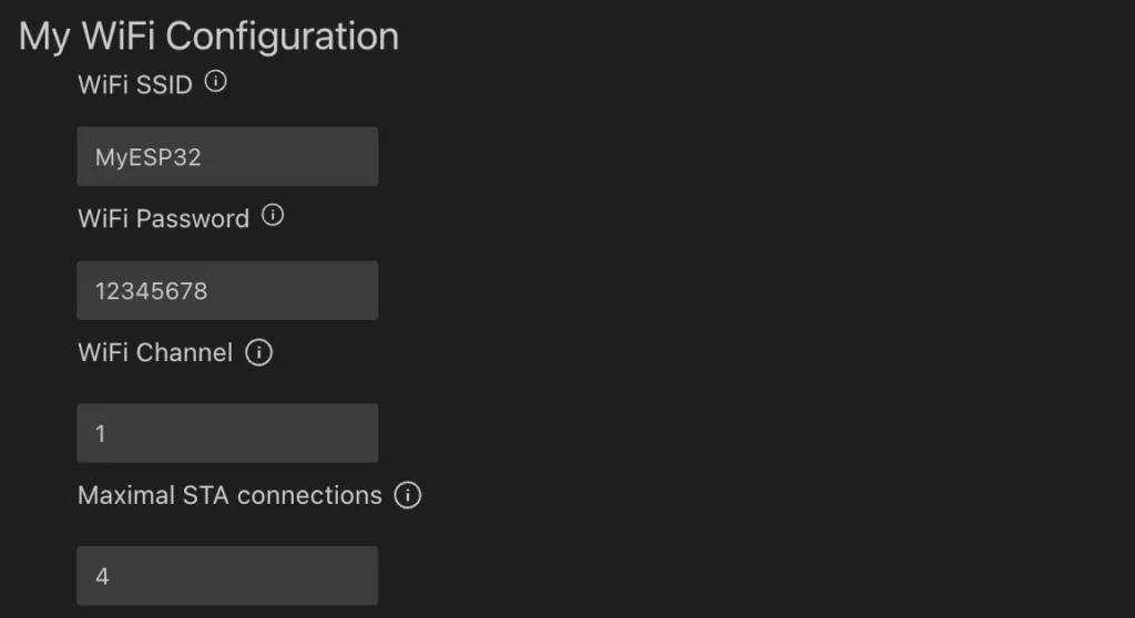
Set your WiFi SSID and password, in this example, we have set to “MyESP32” and “12345678”. You can change it to any value you want. Note that password must be longer than 8 characters, an error will be thrown if it is shorter.
Compile and flash your program
Now you can compile and build your project. If you are using terminal, run idf.py build. If you are using VSCode extension, run command ESP-IDF: Build project.
To flash your program on target ESP32, run idf.py -p [PORT] flash monitor where PORT is the name of the port that ESP32 is connecting to. You can use command ls /dev/cu* to determine which port is corresponding to ESP32. If everything is working properly, you should see the following messages printed on the monitor
I (808) MyApp: WiFi init done.
I (818) MyApp: ESP32 IP:192.168.1.1
Testing your program
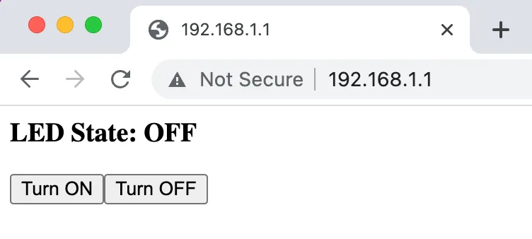
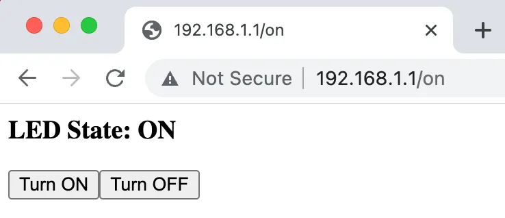
Now ESP32 has been flashed with new program. You should see a WiFi network named “MyESP32” when scanning for WiFi network from your phone or your computer. Open a web browser on your device and enter the IP address of ESP32, which in this project has been set to 192.168.1.1. You should see the following page displayed on your browser.
If you click Turn ON or OFF button, notice that the LED on the breadboard is turned on or off respectively and the web page is also updated.
Wrapping Up
You have learned how to use an ESP32 to control LEDs via a web interface in this post. You created a WiFi network so that client devices may join it and manage accessories connected to ESP32 GPIOs.