· Esp32 · 8 min read
Controlling RGB LED with ESP32 using Bluetooth Low Energy (ESP-IDF)
Bluetooth Low Energy (BLE) is a powerful feature of the ESP32, enabling you to create wireless communication between your device and others. In this guide, we’ll help you get started with BLE development using the ESP-IDF framework, focusing on controlling an RGB LED. You’ll learn how to develop a GATT (Generic Attribute Profile) Server application on the ESP32 with a custom RGB service that allows you to change the LED's color remotely via BLE. With detailed steps and code examples, you’ll be able to control your RGB LED using a smartphone or another Bluetooth-enabled device, opening up endless possibilities for wireless control in your projects.
Introduction
In this article, you will learn how to write a BLE application for ESP32 using ESP-IDF. The aim of the project is to help you get started with BLE development with ESP32. In our project, an application on a smart phone communicates with ESP32 via BLE. A RGB LED is connected to GPIO pins of ESP32. The smart phone will send commands via BLE asking the ESP32 to turn on or off RGB LEDs. Our task is to write firmware for ESP32 to initialise BLE, advertise its existence, handle connection request from the smart phone, receive and handle commands.
Hardware Used
In this article, we will be using the following hardware
| QTY | Component Name | Buy on amazon.com |
|---|---|---|
| 1 | ESP32 WROVER KIT | Amazon |
Affiliate Disclosure: When you click on links in this section and make a purchase, this may result in this site earning a commission at no extra cost to you.
BLE Roles
The first question you may encounter is how to connect the ESP32 and the smart phone via BLE. In BLE communication, a peripheral device advertises its existence by broadcasting radio signals in predefined channels. By listening to those advertising signals, a central device knows about surrounding peripheral devices and may send connection request to establish a connection. In our scenario, the ESP32 is acting as a peripheral device and the smart phone is behaving as a central device. We’ll write firmware to tell ESP32 to advertise its name.
Once connection between ESP32 and the smart phone has been established, the two devices can exchange information, for instance, the smart phone can send commands to ESP32 asking it to do some tasks. In our project, the smart phone sends ON and OFF commands to turn on or off a RGB LED connected to GPIO pins of ESP32. To send commands to ESP32, the smart phone needs to write to a BLE characteristic on ESP32. Hence, in this case, ESP32 is acting as a server and the smart phone is acting as a client device. ESP32 is called a GATT Server (Generic Attribute Profile Server).
BLE Services and Characteristics
In BLE communication between a client and a server, data is grouped into service and characteristic (an attribute table). A service may contain one or more characteristics and contains relevant data types. In our application, we want to control a RGB LED and be able to turn it on or off. We can define a custom service and characteristic to do that job. Since we are building a custom service, it is up to us to define the service and characteristics. For example, we can define our attribute table as follow:
Attribute Table
1 RGB Service
1 RGB Characteristic
Next, we will need to assign a 128 bit (16 bytes) UUID for the Service and Characteristic. A UUID is an unique identifier that we use to reference our Service and Characteristic in Ble communication. You can use an online generator to generate UUIDs. For example, in our project, we will use the following UUIDs
| Item | UUID |
|---|---|
| RGB Service | 3b02556c-4700-4957-812e-b7d297a55600 |
| RGB Characteristic | 3c02556c-4700-4957-812e-b7d297a55600 |
Now let’s dive a little deeper to BLE Attribute Profile. In our application, ESP32 will need to hold a table describing the profile, so that the smart phone can read and interpret what information is available and what it can do. In the table, there are many rows, each row is an attribute. Each attribute has a handle, a type, a set of permissions and a value. For example, we can define a table like below
| Handle | Type | Permission | Value | Note |
|---|---|---|---|---|
| 0x000x | 0x2800 | Read Only, No Authorization, No Authentication | 3b02556c-4700-4957-812e-b7d297a55600 | Service Declaration |
| 0x000x | 0x2803 | Read Only, No Authorization, No Authentication | 3c02556c-4700-4957-812e-b7d297a55600 |
Value Handle (0x000x)
Properties: Write| Characteristic Declaration
0x000x| 3c02556c-4700-4957-812e-b7d297a55600| Write| Opcode (1 byte)| Characteristic Value Declaration
When the smart phone reads this table, it will infer the following information:
- The first row has type 0x2800 which indicates this is a service declaration. This row contains the UUID of the service.
- The second row has type 0x2803 which tells this is a characteristic declaration. It has a UUID which is our custom characteristic UUID above, a value handle which refer to the handle of next row, and the properties is write meaning we can write value to it.
- The final row is the characteristic value declaration, which tells the smart phone that it can write 1 byte of data to it.
Implementing BLE GATTS Server
Create a new project
Now let’s create a new empty project by using Visual Studio Code. Select command ESP-IDF: New project and enter ble_rgb as the name of the project.
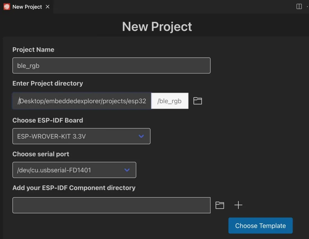
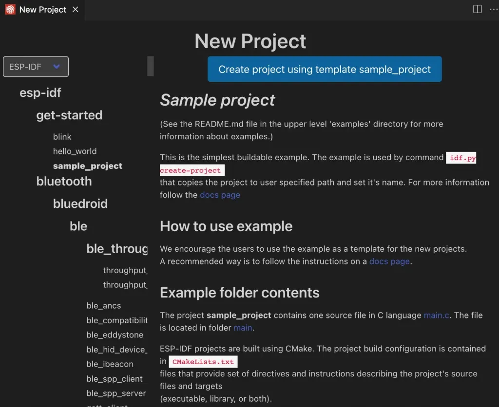
We will base our project on the sample_project template which does not have components or any code in main function. This will allow us to add code sequentially to the project to understand what is happening in each step.
Enabling Bluetooth component
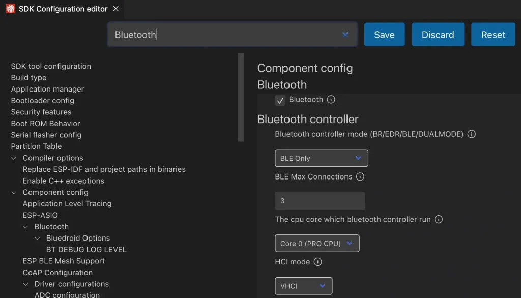
To use BLE in our project, we will need to enable it in project configuration. Run ESP-IDF: SDK Configuration editor (menuconfig) to open SDK configuration interface. Search for bluetooth and check the tick box beside Bluetooth line to enable bluetooth module. This will include necessary files in bluetooth modules during compilation so that we can call bluetooth APIs.
Create custom component
Next, we will create a custom component named ble_rgb which contains functions to initialise bluetooth, setup our service and characteristic, etc. Run ESP-IDF: Create new component. Enter component name as ble_rgb and hit Enter. A new folder named ble_rgb will be created inside the components folder of the project. Now, create several files in ble_rgb folder as follow:
ble_rgb_adv.c: contains logic for handling BLE advertisingble_rgb_gap.c: for writing GAP-related functionsble_rgb_gatts.c: handling GATT Server functions, including configuring our service and characteristic.ble_rgb.c: for initialising bluetooth module and setting up our application
Add the bt component as a requirement in the CMakeLists.txt because our component depends on the bt module in ESP-IDF. CMakeLists.txt would look like this
idf_component_register(SRCS "ble_rgb.c" "ble_rgb_gatts.c" "ble_rgb_adv.c" "ble_rgb_gap.c"
                    INCLUDE_DIRS "include"
                    REQUIRES bt rgb)
`
We will base our project on the GATT Server Example in ESP-IDF. Modifying this template makes our lives much easier compared to writing everything from scratch. You may read the walk through documentation to understand the example, but it is quite extensive and may be a little difficult for beginners to understand.
Full project code is on Github.
The steps when configuring ESP32 as a GATT Server is as implemented in ble_rgb_init() function
void ble_rgb_init(void)
{
    bt_init();
    ble_rgb_gatts_register();
    ble_rgb_gap_register();
    ble_rgb_gatts_app_register();
    ble_rgb_gatts_set_mtu();
}
`
Bluetooth initialisation
The first step when working with BLE is to initialise bluetooth. The function bt_init() in ble_rgb.c performs this task. This function will invoke several ESP_IDF BLE APIs in order to initialise bluetooth.
esp_bt_controller_mem_release();
esp_bt_controller_init();
esp_bt_controller_enable();
esp_bluedroid_init();
esp_bluedroid_enable();
`
You may check the Bluetooth API reference to understand the purpose of each of these functions. It is also explained in details in the GATT Server Example Walkthrough documentation, and is not repeated here.
Register GATTS Event Handler
The next step is to register GATT Server event handler. This is done by calling the function ble_rgb_gatts_register() in ble_rgb_gatts.c. This function in turn calls API esp_ble_gatts_register_callback() from ESP-IDF to register a callback function when a GATT event happens.
What we are interested in is the function gatts_profile_rgb_event_handler() where we handle GATT events:
ESP_GATTS_REG_EVT: this event is fired when we register application ID. Upon receiving this event, we callble_rgb_adv_config()to configure advertising parameters, such as setting device name, connection minimum and maximum interval. Then we callcreate_rgb_service()which invokesesp_ble_gatts_create_service()API to create our RGB service. In our project, we are using 128 bit UUID for the service.ESP_GATTS_CREATE_EVT: after service has been created, this event is fired. This is when we need to callstart_rgb_service()which invokeesp_ble_gatts_start_service()API to start our service. Then we calladd_rgb_characteristic()to add our characteristic. This function usesesp_ble_gatts_add_char()API to add our characteristic to the attribute table. As described above, our characteristic allows writing a single byte, so the characteristic property is set toESP_GATT_CHAR_PROP_BIT_WRITE.ESP_GATTS_WRITE_EVT: when the GATT client request write operation, we receive this event. This is where we handle the commands received from the smart phone. The functionhandle_write_event()extracts the opcode it gets from the smart phone and turn on or off each RGB LEDs.
Register GAP handler
In GAP handler, the event we are interested in is ESP_GAP_BLE_ADV_DATA_SET_COMPLETE_EVT which fired when advertising data is set. Upon receiving this event, we can start advertising by calling esp_ble_gap_start_advertising() API.
Register GATT application identifier
We call esp_ble_gatts_app_register() to register application identifier. As mentioned above, when this function returns successfully, an event ESP_GATTS_REG_EVT is generated and that’s when our service is created.
Testing the GATT Server application
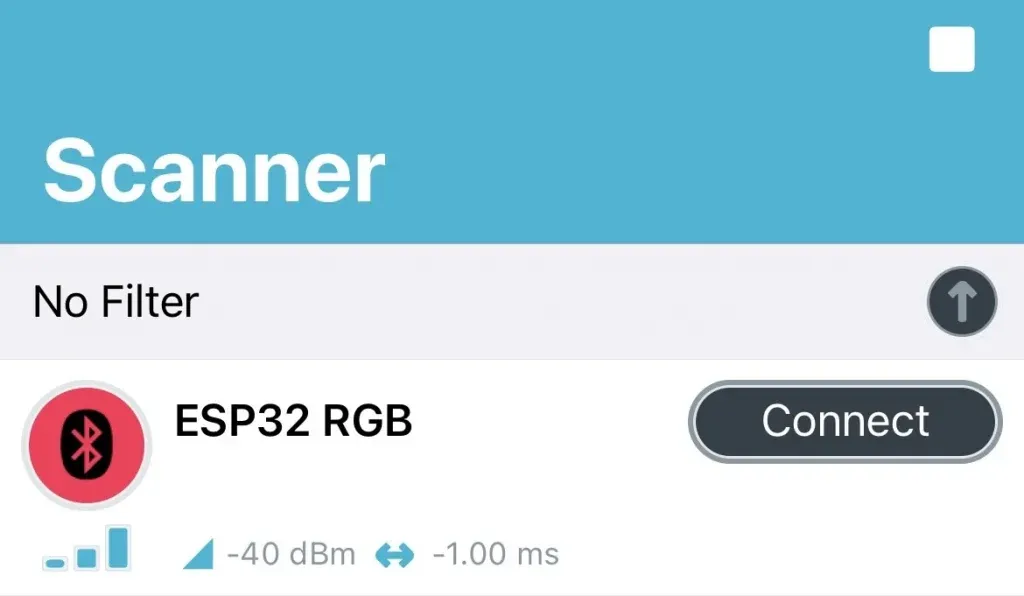
Now flash the program on to the target ESP32 chip. After flashing, the ESP32 will start advertising with name ESP32 RGB which is the name that we set in advertising functions. You can use nRF Connect for Mobile application for iOS and Android to connect to it. Device name ESP32 RGB is shown in the device list when scanning
Once the nRF Connect app has successfully connected to ESP32 device, you will see the service and characteristic.
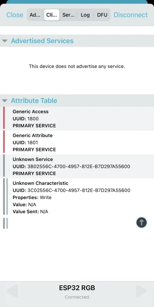
To test that the smart phone can control the RGB LED on ESP32 board, send a command code 0x01 to it. You should see the LED is turned on. If you send a command code 0x02, the GREEN LED is on. The BLUE LED is on if you send command code 0x03. To turn off all LEDs, you send command 0x04.
Wrapping Up
In this article, you have learnt how to create a GATT Server application with ESP32 to control RGB LED. It is quite a steep learning curve, but with some time and effort, you can understand and adapt it for other BLE applications. Thanks for reading.