· Esp32 · 5 min read
Measuring analog inputs with ESP32 ADC (ESP-IDF)
The ESP32 comes with built-in analog-to-digital converters (ADC) that allow you to read analog signals from sensors and other devices. In this guide, we’ll walk you through how to use the ESP32 ADC with the ESP-IDF framework to measure analog inputs. You’ll learn about the ADC pins on the ESP32, how to configure the ADC for different resolutions and sampling rates, and how to calibrate the ADC for more accurate readings. We’ll also provide an example project where you can read values from an analog sensor, process the data, and display it. By the end of this tutorial, you’ll have a solid understanding of how to utilize the ESP32 ADC for your own projects.
Introduction
In this article, you will learn about ESP32 Analog to Digital Converter. ESP32 has two ADC modules (named ADC1 and ADC2). There are 8 IO pins that are connected to ADC1 and 10 pins that are connected to ADC2. To measure analog input signals, you have to connect them to IO pins that are connected to either of the ADC modules. You will learn what those pins are, how to do calibration for ADC, how to use APIs in ESP-IDF to configure the ADCs. You will implement a simple project using ADC to read an analog input pin and print values to a console.
ESP-IDF ADC APIs
ADC libraries
When working with ADC using ESP-IDF, you need to include two libraries: the adc driver defined in components/driver/include/driver/adc.h and the library for ADC calibration esp_adc_cal.h. You need to include the following headers in your code
#include "driver/adc.h"
#include "esp_adc_cal.h"
ADC Pins
The following table describes the IO pins that are associated with ADC1 and ADC2 modules. As can be seen from the table, there are 8 ADC1 channels, numbered from 0 to 7 and 10 ADC2 channels, numbered from 0 to 9. If you are measuring analog signal from pin GPIO34, for example, you will refer to it as ADC1_CHANNEL_6 in your code.
| ADC1 channel | GPIO pin | ADC2 channel | GPIO pin |
|---|---|---|---|
| ADC1_CHANNEL_0 | GPIO36 | ADC2_CHANNEL_0 | GPIO4 |
| ADC1_CHANNEL_1 | GPIO37 | ADC2_CHANNEL_1 | GPIO0 |
| ADC1_CHANNEL_2 | GPIO38 | ADC2_CHANNEL_2 | GPIO2 |
| ADC1_CHANNEL_3 | GPIO39 | ADC2_CHANNEL_3 | GPIO15 |
| ADC1_CHANNEL_4 | GPIO32 | ADC2_CHANNEL_4 | GPIO13 |
| ADC1_CHANNEL_5 | GPIO33 | ADC2_CHANNEL_5 | GPIO12 |
| ADC1_CHANNEL_6 | GPIO34 | ADC2_CHANNEL_6 | GPIO14 |
| ADC1_CHANNEL_7 | GPIO35 | ADC2_CHANNEL_7 | GPIO27 |
| ADC2_CHANNEL_8 | GPIO25 | ||
| ADC2_CHANNEL_9 | GPIO26 |
ADC Input Voltage range
Before feeding into the ADC modules, the analog signal is attenuated. Depending on the attenuation parameter, the range of ADC is different. The table below listed the attenuation parameters and their respective input ranges. The table shows that the ESP32 ADC only works reliably in certain range. This is a limitation of the ESP32 ADC.
| Attenuation parameter | Input range (mV) | Note |
|---|---|---|
| ADC_ATTEN_DB_0 | 100 ~ 950 | No attenuation (0dB) |
| ADC_ATTEN_DB_2_5 | 100 ~ 1250 | 2.5 dB attenuation |
| ADC_ATTEN_DB_6 | 150 ~ 1750 | 6 dB attenuation |
| ADC_ATTEN_DB_11 | 150 ~ 2450 | 11 dB attenuation |
To setup attenuation parameter for a channel of ADC1, you use the API adc1_config_channel_atten(). For example, to set 11 dB attenuation for ADC1 channel 6, you call
adc1_config_channel_atten(ADC1_CHANNEL_6, ADC_ATTEN_DB_11);Similarly, to configure attenuation for a ADC2 channel, you use adc2_config_channel_atten() function in the adc driver.
ADC Calibration
Due to variation in internal reference voltage of different ESP32 chips, the ESP32 ADCs needs to be calibrated before using. One way of doing calibration is using the true ADC reference voltage stored in eFuse. This value is measured and written to the ESP32 when it was made at factory.
To calibrate the ADCs, you use the API esp_adc_cal_characterize(). For example, to calibrate ADC1 at 11 dB attenuation, you call the following function
esp_adc_cal_characteristics_t adc1_chars;

esp_adc_cal_characterize(ADC_UNIT_1, ADC_ATTEN_DB_11, ADC_WIDTH_BIT_DEFAULT, 0, &adc1_chars);
The ADC calibration result is stored in adc1_chars.
Configure ADC bit width
To configure the ADC1 bit width, you use the API adc1_config_width() and pass in the value of bit width. Accepted values are ADC_WIDTH_BIT_9, ADC_WIDTH_BIT_10, ADC_WIDTH_BIT_11, ADC_WIDTH_BIT_12 or ADC_WIDTH_BIT_DEFAULT. By default, ADC1 use 12-bit.
Capture raw ADC value
To get raw ADC1 value, you call adc1_get_raw() and specify the ADC1 channel you want to capture. You need to call adc1_config_width() before the first time this function is called. For example, to get raw channel 6 ADC1 raw value, you use
adc1_config_width(ADC_WIDTH_BIT_DEFAULT);
int raw_value = adc1_get_raw(ADC1_CHANNEL_6);
Similarly, to get raw ADC2 value, you use adc2_get_raw().
Convert raw value to mV (after calibration)
To convert the raw value to milivolt value and take into account calibration, you use the API esp_adc_cal_raw_to_voltage(). This function takes two parameters:
adc_readingis the raw value captured byadc1_get_raw()oradc2_get_raw()charis a pointer to ADC characteristics obtained after calibration (after callingesp_adc_cal_characterize())
For example, you can use this snippet to get the mV value from ADC1 channel 6
uint32_t mV = esp_adc_cal_raw_to_voltage(adc1_get_raw(ADC1_CHANNEL_6), &adc1_chars);ESP-IDF ADC Example
Project description
In this section, you will implement a simple project using ADC. Connect a potentiometer to GND, 3.3V and GPIO34 of ESP32. You will read and log the ADC value measured from GPIO34. As mentioned previously, GPIO34 corresponds to ADC1 Channel 6. So in the project, you will try to calibrate ADC1, then read raw value from its channel 6 and convert to milivolt value, and finally logs it to console every 100 ms.
Component Used
The following table describes the components used in the project
| QTY | Component Name | Buy on amazon.com |
|---|---|---|
| 1 | ESP32 DevKit C | Amazon |
| 1 | Potentiometer | Amazon |
| 1 | Breadboard | Amazon |
| 1 | Jumper Wire Kit | Amazon |
Affiliate Disclosure: When you click on links in this section and make a purchase, this may result in this site earning a commission at no extra cost to you.
Code
#include <stdio.h>
#include <stdlib.h>
#include "esp_log.h"
#include "freertos/FreeRTOS.h"
#include "freertos/task.h"
#include "driver/adc.h"
#include "esp_adc_cal.h"

static const char *TAG = "ADC EXAMPLE";

static esp_adc_cal_characteristics_t adc1_chars;

void app_main(void)
{
    uint32_t voltage;

    esp_adc_cal_characterize(ADC_UNIT_1, ADC_ATTEN_DB_11, ADC_WIDTH_BIT_DEFAULT, 0, &adc1_chars);

    ESP_ERROR_CHECK(adc1_config_width(ADC_WIDTH_BIT_DEFAULT));
    ESP_ERROR_CHECK(adc1_config_channel_atten(ADC1_CHANNEL_6, ADC_ATTEN_DB_11));

    while (1)
    {
        voltage = esp_adc_cal_raw_to_voltage(adc1_get_raw(ADC1_CHANNEL_6), &adc1_chars);
        ESP_LOGI(TAG, "ADC1_CHANNEL_6: %d mV", voltage);
        vTaskDelay(pdMS_TO_TICKS(100));
    }
}
How the code works
If you have followed along with previous section, you can understand this piece of code easily. The code starts with calibrating ADC1 for 11dB attenuation using esp_adc_cal_characterize(). Then it configures ADC1 bit width and attenuation parameter using adc1_config_width() and adc1_config_channel_atten(), respectively. In the main loop, it repeatedly call adc1_get_raw() and esp_adc_cal_raw_to_voltage() to capture raw value and convert it to milivolt. Finally, it print logs using ESP_LOG module and delay 100 ms using vTaskDelay() API from freeRTOS.
Build, flash and run program
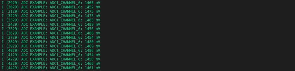
To build, flash and run program, you can run the command on a terminal
idf.py build flash monitor -p [PORT]You should see output logs like this
Wrapping Up
In this article, you have learnt about ESP32 ADC and APIs in ESP-IDF to work with it. If you want to learn more, check out ESP32 official documentation. Thanks for reading.