· Stm32 · 5 min read
STM32 I2C Master using HAL
The STM32 microcontrollers provide a robust I2C module for communication with peripheral devices. In this tutorial, you’ll learn how to configure and use the I2C interface on STM32 as a master using the STM32 HAL (Hardware Abstraction Layer). We’ll guide you through the process of setting up the I2C module in STM32CubeIDE, configuring it to communicate with an I2C slave device, and reading data from the slave. The tutorial also includes logging the received data to a console for easy monitoring. By the end of this guide, you’ll be equipped to handle I2C communication for your STM32 projects.
Introduction
I2C (I nter I ntegrated C icuit) is a protocol commonly used in embedded systems to exchange data between devices involving a master and one or more slave devices. The protocol only uses two wires: one clock line (SCL) and one data line (SDA). STM32 chips have dedicated hardware blocks implementing this protocol. In this article, you will learn how to implement a project using STM32 I2C peripheral as a Master device.
To compile and run your code on STM32 hardware, it is recommended that you have a STM32 development kit such as
- STM32 Nucleo-64 Development Board with STM32F303RE MCU
- STM32 Nucleo-64 Development Board with STM32F401RE MCU
- STMicroelectronics NUCLEO-F446RE STM32F446RET6 MCU
Affiliate Disclosure: When you click on links in this section and make a purchase, this may result in this site earning a commission at no extra cost to you
Project description
In our project, STM32 behaves as a Master device which controls the clock line and read data from a slave device. The purpose of our project is to demonstrate project creation using STM32CubeIDE, understanding how to configure I2C peripheral in STM32 and how to use STM32 HAL I2C library to read data.
In our project, we will be using I2C slave with the following parameters:
- Slave address: 0x11
- I2C master can read 5 bytes of data (0x01, 0x02, 0x03, 0x04, 0x05) from the I2C slave
This slave device is implemented using Nordic PCA10040 development kit running nRF52 TWIS program. We will log the data received from I2C slave to UART console using USART3.
Hardware connection
We will use STM32 DE1 development kit with STM32F103VBT6 chip. Similar with previous article, we will use the CJMCU-2232HL module to log messages to an UART terminal. We will use PCA10040 board, which has a Nordic nRF52832 acting as an I2C slave device.
Connect pins according to table below
| STM32 pin | PCA10040 pin | Note |
|---|---|---|
| PB10 | 27 | I2C SCL pin |
| PB11 | 26 | I2C SDA pin |
Project Implementation
Create a new project in STM32CubeIDE
The first step is to create a new project in STM32CubeIDE. Click File > New > STM32 Project and open Target Chip Selector. Select STM32F103VBT6 as the target chip, then enter a name for the project and hit Finish. You should be familiar with these steps if you have followed our previous articles.
Choosing I2C instance
The STM32F103VBT6 has two I2C hardware blocks that you can use: I2C1 and I2C2. Other STM32 variants may have more or less I2C peripherals which you need to check the chip’s datasheet. One limitation of STM32 I2C block compared with other chips is the SCL and SDA pins are hardwired to specific IO pins and you can not select pins programmatically. Other chips, such as Nordic nRF52, provide capability to choose any IO pins for I2C module which offers greater flexibility. The table below listed IO pin of I2C1 and I2C2 modules in STM32F103VBT6.
| Pin | Description |
|---|---|
| PB7 | I2C1_SDA |
| PB6 | I2C1_SCL |
| PB11 | I2C2_SDA |
| PB10 | I2C2_SCL |
As described in previous section, we will be using I2C2 instance in our project. To enable the I2C2 instance, click on I2C2 on the left panel of Pinout & Configuration tab, then select I2C in I2C2 Mode and Configuration tab.
Configuring I2C parameters
To configure I2C parameters, such as clock speed, click on the Paramter Settings. The I2C supports both standard mode with speed of 100 kHz and Fast mode with speed of 400 kHz. In our project, select Fast Mode as I2C speed mode, and I2C Clock speed of 400 kHz.
Enabling USART3 for logging
Similar to previous post, select USART3 on the left panel of Pinout & Configuration, select Asynchronous mode and set baud rate of 115200. Since I2C2 is enabled, we will need to use PD9 as RX pin and PD8 as TX pin, instead of PB10 and PB11 in previous project.
Click Save and Yes to generate code automatically.
I2C initialisation
If you inspect main.c, you will see that the following function has been added automatically based on your selection. This function calls HAL_I2C_Init() with a configuration structure to initialise the I2C2.

Reading data from I2C slave using HAL driver
To read data from I2C slave device, add the following code to main.c
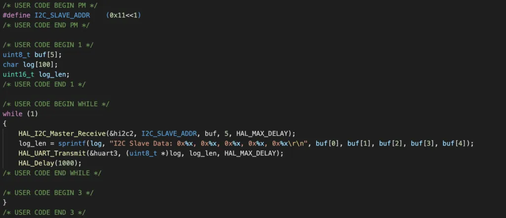
This code snippet read data from the I2C slave with address I2C_SLAVE_ADDR by calling the API HAL_I2C_Master_Receive() every second. The 7 bit slave address must be shifted to the right in the argument of this function. The data is written to a buffer of 5 bytes and then flushed to USART3 by calling HAL_UART_Transmit() as you have seen in previous article.
Other HAL I2C functions are defined in Drivers/STM32F1xx_HAL_Driver/Src/stm32f1xx_hal_i2c.c. To transmit data from the master to the slave, you call HAL_I2C_Master_Transmit() function. Similar to when receiving data from the slave, you need to specify the I2C instance, the slave address, pointer to a transmit buffer, length of the buffer and a timeout value. Note that HAL_I2C_Master_Transmit() and HAL_I2C_Master_Receive() are blocking functions, meaning that these functions will return when the transfer is completed. To use non-blocking mode, you use HAL_I2C_Master_Transmit_IT() and HAL_I2C_Master_Receive_IT() functions instead.
Once you compile and flash the program, you will see the following log messages printed on UART terminal every 1 second
I2C Slave Data: 0x1, 0x2, 0x3, 0x4, 0x5
I2C Slave Data: 0x1, 0x2, 0x3, 0x4, 0x5
Wrapping Up
In this article, you have learnt about the STM32 I2C peripheral in Master mode by working on a practical project. STM32 I2C module can also be configured to operate in slave mode. To go further from here, you can dig deeper into the source code stm32f1xx_hal_i2c.c to see how things work. Thanks for reading.