· Nordic · 8 min read
Using nRF52 as I2C Slave with TWIS peripheral
While the nRF52 is often used as an I2C master, it’s fully capable of acting as a slave device too — thanks to the TWIS (TWI Slave with EasyDMA) peripheral. In this detailed guide, we’ll explore the capabilities of TWIS and how it differs from the standard TWI interface. Using the nrf_drv_twis driver from the nRF5 SDK, we’ll walk through initialization, buffer handling, and event-driven communication to build a simple I2C slave project. Whether you're connecting your nRF52 to another microcontroller or a Raspberry Pi, this tutorial will help you integrate seamlessly as an I2C slave device.
Introduction
I2C is a common communication protocol between a master device and a slave device using two wires. One wire is used for transmitting data signal (SDA line), and one wire is for clock signal (SCL line). The master device controls the communication and decides when to send and receive data from the slave. nRF52 chips, such as nRF52832, have dedicated hardware blocks implementing I2C protocol. If you want nRF52 plays a role of I2C master, you use the TWI or TWIM peripheral. In case you need nRF52 to act as an I2C slave device, you can use the TWIS module. In this article, we look at how to use nRF52 TWIS peripheral in applications where nRF52 works as I2C slave. We will talk about:
- The TWIS peripheral’s features
- The nrf_drv_twis driver in nRF5 SDK 17.1 to control TWIS
- A simple sample project with TWIS
To compile and run your code on real nRF52 hardware, it is recommended that you have a nRF52 development kit such as
Affiliate Disclosure: When you click on links in this section and make a purchase, this may result in this site earning a commission at no extra cost to you.
The TWIS peripheral
Address space
The TWIS peripheral, like any other peripherals in nRF52, is allocated an address space in memory. This space is 4 kB (or 0x1000 bytes in hexadecimal) and contains 1024 32-bit registers. The TWIS module’s operation relies on these registers. In nRF52832, there are two TWIS instances, TWIS0 and TWIS1, which reside at base addresses of 0x40003000 and 0x40004000, respectively. Because one peripheral can share its address space with other peripherals, you need to make sure two peripherals are not being used at the same time in your application so that they do not conflict with each other. The TWIS0 instance shares resources with TWI0, TWIM0, SPI0, SPIM0, SPIS0 while the TWIS1 instance has the same base address with TWI1, TWIM1, SPI1, SPIM1, SPIS1.
Direct RAM access using EasyDMA
During operation, the TWIS needs to store data that it receives from the master, and it needs a space somewhere to keep data to send to the master. These memory buffers are kept in RAM, and the TWIS can access these RAM region directly with the help of EasyDMA block. The TWIS actually uses two EasyDMA channels, one for receiving buffer, and one for transmitting buffer. There are 3 registers to control each EasyDMA channel: PTR, MAXCNT and AMOUNT. The PTR register points to the start of the buffer region, the MAXCNT register specifies the region’s length, and the AMOUNT register tells how much data was written to RAM or read from RAM during one transaction.
Pin selection
SCL and SDA pins of the TWIS peripheral are not hard-wired to any specific I/O pins. Their connection to physical I/O pins is programed by software and those pins are mapped to physical pins by specifying pin number in PSEL.SCL and PSEL.SDA registers respectively.
The nrf_drv_twis library
The nRF5 SDK provides library nrf_drv_twis to interact with the TWIS peripheral. It simplifies your jobs as you don’t need to work directly with TWIS registers. In this section, we will take a look at this driver and learn how to use its APIs to control the TWIS.
Include the driver in your project
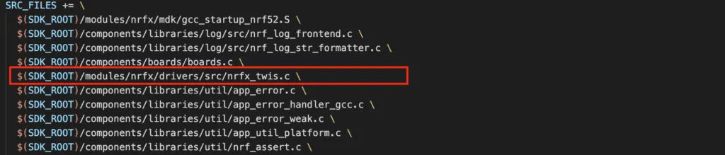
To use nrf_drv_twis function calls, some source files need to be included in your Makefile. The nrf_drv_twis header file nrf_drv_twis.h is defined in nRF5_SDK_17.1.0_ddde560/integration/nrfx/legacy folder. If you take a close look at this file, you will see that functions in this driver are actually implemented in nrfx_twis driver and this driver is just providing compatibility with legacy APIs. Hence, in your source file list, you need to include nrfx_twis.c as a dependency and nrfx_twis.h is defined in nRF5_SDK_17.1.0_ddde560/modules/nrfx/drivers/include. The snippet below shows how you can include required files in your project:
Enabling the TWIS instance in sdk_config.h
By now, you probably are familiar with how a project is structured in nRF5 SDK and steps to include a driver. After including the required files, you need to enable the TWIS instance that you want to use in project configuration sdk_config.h. Inside the nrf_drv_twis driver, it checks if an instance is enabled, so if you don’t do this step, you will get complains from the compiler. The below snippet shows how you can enable the TWIS1 instance, note that there are some definitions used internally by the driver and you need to add them:
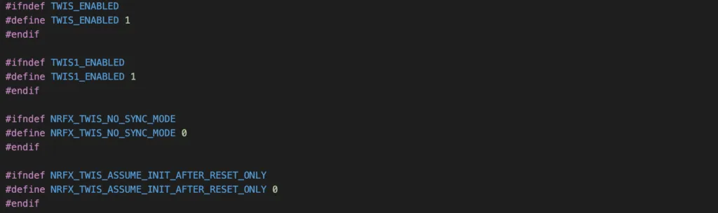
In some example projects in nRF5 SDK, you might notice that there are definitions with prefix NRFX_, such as NRFX_TWIS_ENABLED or NRFX_TWIS1_ENABLED which might cause some confusion as which one you should enable. As I have mentioned a few times in previous articles, if TWIS_ENABLED and NRFX_TWIS_ENABLED coexist, TWIS_ENABLED will be used and NRFX_TWIS_ENABLED will be ignored.
Initialising TWIS instance
The TWIS driver must be initialised before it is used. To initialise a TWIS instance, you use the function nrf_drv_twis_init() which is the same as nrfx_twis_init().

You can use the macro NRF_DRV_TWIS_INSTANCE() to define a TWIS instance that you will use and pass its address to the first argument of initialisation function. You then need to tell the function in the second argument about the TWIS configuration, including its slave address, which pin is used as SCL, which pin is used as SDA. Finally, you provide a callback function to handler TWIS events. Here are some of the events generated by the TWIS:
TWIS_EVT_READ_REQ: this event is generated when a read request is detected. In other words, the master has asked data from the TWIS by sending the TWIS’s address with the read bit on the SDA line.NRFX_TWIS_EVT_READ_DONE: when the data has transferred to the master, this event is generated and you can check thetx_amountto see how much data was sent.NRFX_TWIS_EVT_WRITE_REQ: if the master wants to send some data to the TWIS, it sends the TWIS’s address with the write bit on the SDA line. Upon detecting this condition, this event is generated to the application to process.TWIS_EVT_WRITE_DONE: when data has been received from the master and written to buffer.NRFX_TWIS_EVT_READ_ERROR,NRFX_TWIS_EVT_WRITE_ERRORorNRFX_TWIS_EVT_GENERAL_ERROR: fires if an error has happened during the data transfer process
Enabling the TWIS instance
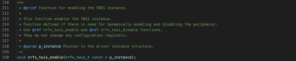
To enable the TWIS instance, you use function nrf_drv_twis_enable() and pass in the address of the instance variable. This function is the same as nrfx_twis_enable(). The driver must be enabled before it is used.
Preparing data buffer for sending data to master
As noted previously, when a TWI master wants data from the TWIS, it will send the TWIS’s address with the read bit. Upon detecting this condition, the TWIS will generate an event TWIS_EVT_READ_REQ which you need to handle. You should then call nrfx_twis_tx_prepare() to prepare the transmitting buffer. You need to tell this function the address of the transmit buffer in RAM and its size. The buffer needs to be placed in RAM since the TWIS use EasyDMA block to access RAM directly as discussed in previous section. If not, an error will occur.

Preparing data buffer for receiving data from master
Similarly, when the TWI master needs to send data to TWIS, it you be notified by NRFX_TWIS_EVT_WRITE_REQ. You can call nrfx_twis_rx_prepare() to specify the buffer which is reserved to receive data from the master. This buffer needs to be placed in RAM region as well.

TWIS Example Project
To help you solidify the TWIS knowledge, we will walk though a simple project which use TWIS peripheral to demonstrate how to use nrf_drv_twis driver.
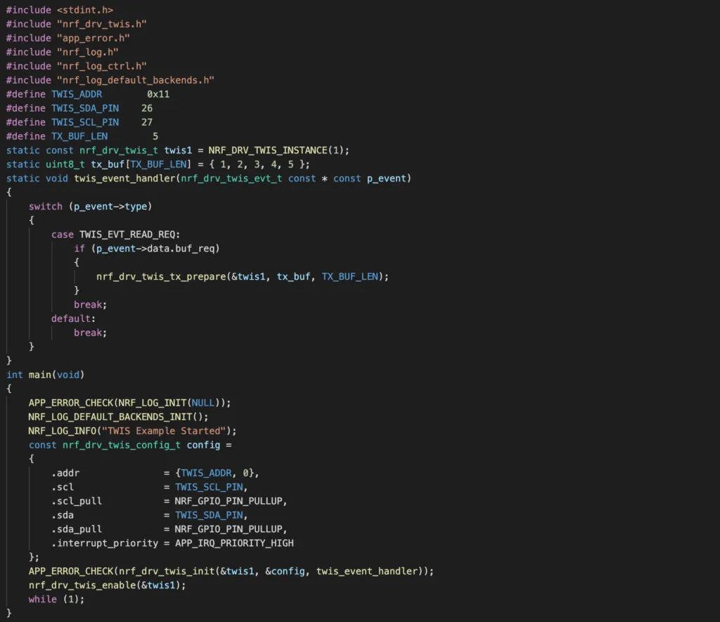
- In this project, we use TWIS1 instance to configure nRF52832 as a TWI Slave device. We will use the development board PCA10040.
- The address of this TWI Slave will be set as 0x11. It can be any number that you like. Unlike with most sensors where their addresses are fixed, you can change the slave address of TWIS programmatically. Just make sure this value does not conflict with any other address on the same I2C bus.
- The SDA and SCL lines of TWIS1 instance will be mapped to physical pins 26 and 27, respectively with pull up resistors. Since the pins are programmable, you can also use any available I/O pins. This is very flexible compared with other chips.
- We will set up a buffer to 5 bytes, containing values from 1 to 5. The TWI Master can read these values by requesting address 0x11 and read bit. This is arbitrary and you can set up your buffers as you want.
Code
We will start by a template project which include NRF_LOG module as described in our previous article, starter project link can be found on Github here. Follow the following steps:
- Download the project files to your computer
- Enabling the TWIS1 instance in sdk_config.h as above section.
- Add the following code to your
main.c.
Final project link can be found on Github here.
Testing the program
To test the above code, you will need a TWI Master device. I have written another article about how to configure nRF52 as an I2C Master here and you can refer to that article on how to test the code in this guide.
Wrapping Up
It is not every common to see nRF52 behaving as I2C slave devices. As nRF52 is very powerful, they are mainly used in I2C Master mode to communicate with sensors or other modules. However, as it is configurable via software, it is sometimes useful to use nRF52 TWIS to test I2C Master modules. Hope you learn a thing or two from this guide. Thanks for reading.