· Nordic · 7 min read
Using NRF52 as SPI Slave with SPIS peripheral
While the nRF52 series is often used as an SPI master, it can also serve as a reliable SPI slave thanks to the SPIS (SPI Slave with EasyDMA) peripheral. In this guide, we’ll explore how SPIS works, its advantages in slave mode communication, and how to configure it using the nrf_drv_spis driver from the nRF5 SDK. From setting up buffers and handling transfers to responding to master requests, we’ll walk through everything you need — including a working example project to get your nRF52 talking as a slave device on the SPI bus.
Introduction
Although in most applications using Serial Peripheral Interface (SPI), nRF52 is configured as a Master device, it is sometimes useful to use nRF52 as a SPI Slave to transfer data to other devices. To configure nRF52 as a SPI Slave, you can use SPIS hardware module inside the chip. In this post, you will learn how to use the SPIS peripheral in nRF52. More specifically, you will learn about:
- SPIS peripheral operation, instances and registers
- The
nrf_drv_spislibrary to control SPIS - Explanation of a sample project using nRF52 SPIS in nRF5 SDK to see how to nrf_drv_spis APIs are used.
To compile and run your code on real nRF52 hardware, it is recommended that you have a nRF52 development kit such as
Affiliate Disclosure: When you click on links in this section and make a purchase, this may result in this site earning a commission at no extra cost to you.
The nRF52 SPIS peripheral
In the previous article, you learnt about the SPI master peripherals in nRF52 which include SPI and SPIM modules. A SPI master device generates clock signal, controls CS line and decides when to start a transaction. A SPI slave device responses to the signals from the master and sends out data on the MISO line or reads data on the MOSI line. The SPIS peripheral is a dedicated hardware block in nRF52 and works as a SPI Slave device.
There may be more than 1 instance of SPIS in nRF52. For example, nRF52832 has 3 SPIS instances (SPIS0, SPIS1 and SPIS2). Remember that for nRF52, each peripheral has an ID and a base address and is allocated 1024 x 32-bit registers. If two peripherals share the same ID and base address, they must not be used at the same time. The SPIS instances share resources with other peripherals which you need to take into account when building your project. For instance, SPIS0 has the same address space with SPI0, SPIM0, TWI0, TWIM0 and TWIS0.
The SPIS peripheral uses EasyDMA for directly accessing RAM (read and write). To control its operation, EasyDMA uses some registers:
PTR: stores the address of the RAM buffer, e.g. where in RAM to write data to or where to read data from RAM.MAXCNT: contains the maximum number of bytes that you want to read or to writeAMOUNT: when EasyDMA completes a read or write operation to RAM, this register will be updated and tell how many bytes were read or written successfully.
The SPIS peripheral uses two EasyDMA blocks to manage two buffers in RAM. One is transmit buffer which stores data to send to the master. The other one is receive buffer which stores data coming from the master.
- The EasyDMA which controls accessing RXD buffer (receive buffer) uses
RXD.PTRregister to store buffer address,RXD.MAXCNTregister to specify the maximum number of bytes in the buffer, andRXD.AMOUNTregister to tell how many bytes received in the last transaction. - Similarly, the EasyDMA block which controls the TXD buffer (transmit buffer) uses
TXD.PTR,TXD.MAXCNTandTXD.AMOUNTregisters for accessing RAM.
Since the SPIS peripheral and CPU both have access to the same RAM regions, a hardware based semaphore is used to enable safe accessing the buffers. This is achieved by using tasks and event registers. The CPU acquires semaphore by triggering TASKS_ACQUIRE task, and should check for EVENTS_ACQUIRED to make sure semaphore has been acquired. When it no longer requires access to RAM, it triggers TASKS_RELEASE to release the semaphore so that SPIS can use it.
The nrf_drv_spis library
As you see in the previous section, to control SPIS module, you need to control its registers and manage their operations according to nRF52 datasheet. You’ll need to know all tasks and events registers as described previously and control them. That’s a fairly complicated task. Fortunately, you don’t usually need to care about the module’s registers and how they operate internally. Nordic’s engineers have spent time and energy to build nrf_drv_spis library which encapsulate most of internal working detail. They provide some high level APIs which are much easier to use. In this section, we will learn how to use the nrf_drv_spis library in nRF5 SDK to control the operation of SPIS peripheral.
Include the library in your project
First, you need to include nrfx_spis.c and nrf_drv_spis.c in your source file list. If you are interested in how they are implemented, you can go to the corresponding folder and try to understand their code. Sometimes, you may also need to do that if there’s a bug in a driver that was not known at the time of release.

Enabling the SPIS peripheral in sdk_config.h
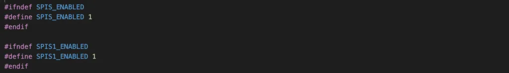
Next, you need to enable the SPIS instance you want to use in sdk_config.h. Supposed you want to use SPIS1 instance, you will need to enable the following settings. These settings are used internally by some source files and if you don’t enable them, you’ll get compiler’s complaint.
Initialisation
To initialise the SPIS peripheral, you use the API nrf_drv_spis_init(). Similar to SPI/SPIM instances covered in previous article, you will need to pass in pointer to a SPIS instance, a pointer to SPIS configuration and an event handler. You can use the macro NRF_DRV_SPIS_INSTANCE to define the SPIS instance that you want to use.

Setup buffer for single transaction
To setup buffer for single transaction, you use the function nrf_drv_spis_buffers_set(). This function is the same as nrfx_spis_buffers_set(). This function requires a SPIS instance and transmit and receive buffer address and length as arguments.
![]()
SPIS project example
In this section, we will analyse the SPIS project example in nRF5 SDK version 17.1. Since it’s simple enough, I won’t provide another example project in this article. Open main.c from folder nRF5_SDK_17.1.0_ddde560/examples/peripheral/spis and inspect the code in there. As you can see, in this example:
They use
NRF_DRV_SPIS_INSTANCEto define the SPIS1 instance. Note that SPIS1 instance is also enabled insdk_config.has described in previous section.They set up a receive buffer
m_rx_bufand transmit bufferm_tx_bufin RAM.They initialise the NRF_LOG module to print out log messages. You can check out our previous article about enabling the NRF_LOG module here.
They initialise the SPIS driver by calling
nrf_drv_spis_init(), pass in the SPIS instance variable defined earlier, a configuration structure specifies which pins are used for SPI transfer, and an event handlerspis_event_handler.In the main loop, a flag
spis_xfer_doneis set to false initially, then thenrf_drv_spis_buffers_set()function is called to setup buffer for a single transfer. Then it goes to sleep mode waiting for a transaction occurs. When a SPI transaction completes, the event handler toggle the flagspis_xfer_done()and it flushes out the log message to console.
Testing the SPIS project
To test the above program, you’ll need two PCA10040 boards, one board as SPI Slave, the other board as SPI Master.
SPI Slave board
To test the project, compile and flash the project to your PCA10040 board by running make flash. In this example, the NRF_LOG UART backend is used, so you will need a UART terminal to see log messages. Set the baud rate to 115200 baud. On MacOS or Linux, you can use screen program to see log messages.
SPI Master board
Compile and flash the example project spi in /nRF5_SDK_17.1.0_ddde560/examples/peripheral/spi. Then open other screen program in other terminal with 115200 baud.
Connect SPI Master and SPI Slave boards
You now need to connect two boards together using 4 wires as follow. These are the pins defined in source code. Since SPI pins are configurable, you can choose any other I/O pins. If you do so, you need to change the connection accordingly.
Pin    SPI Master board    SPI Slave board
CS            31                 31
CLK           26                 26
MISO          30                 30
MOSI          29                 29
After connecting two boards, you will see the following messages:
From SPI Master side
app: Transfer completed. app: Received: app: 4E 6F 72 64 69 63 |Nordic From SPI Slave side
app: Transfer completed. Received: Nordic
If you see these messages, that means the SPIS peripheral is working properly. It is configured to send out the text Nordic to the SPI Master device and receive the same string from the Master.
Wrapping Up
Unlike other examples in nRF5 SDK, the SPIS example is quite straight-forward and easy to understand. Although nothing fancy is provided here, this guide serves as a complete overview of SPIS hardware and its usage, so you don’t need to go around and look for bits and pieces of information everywhere. Thanks for reading.