· Stm32 · 7 min read
STM32 timer with STM32CubeIDE and HAL
Timers are crucial for managing time-based tasks in embedded systems, and STM32 microcontrollers offer a variety of hardware timers to meet these needs. In this article, you’ll learn the basics of STM32 hardware timers and how to configure them using STM32CubeIDE and the STM32 HAL (Hardware Abstraction Layer). We’ll guide you through setting up a timer, configuring it for periodic events, and utilizing timer interrupts. By the end of this guide, you’ll have a foundational understanding of STM32 timers, ready to use them for applications like PWM generation, delays, and time-based event handling.
Introduction
Timer is a hardware block found in most microcontrollers and is used in many applications. Therefore, mastering timer usage is usually required when working with any chip platform. In this article, we will learn about STM32 hardware timers and how to use them in STM32CubeIDE. If you are a complete beginner to STM32 development, you might get overwhelmed with the amount of information presented in STM32 documentation. This guide hopefully helps you get the first step in understanding STM32 timers.
To compile and run your code on STM32 hardware, it is recommended that you have a STM32 development kit such as
- STM32 Nucleo-64 Development Board with STM32F303RE MCU
- STM32 Nucleo-64 Development Board with STM32F401RE MCU
- STMicroelectronics NUCLEO-F446RE STM32F446RET6 MCU
Affiliate Disclosure: When you click on links in this section and make a purchase, this may result in this site earning a commission at no extra cost to you.
STM32 Timer hardware
The first thing you need to know about STM32 timers is how many timer instances each chip has. Depending on the chips, there may be many instances available to use. To know the exact number of timers, you can check its datasheet. For instance, the STM32F103VBT6 chip has 4 timers, including 1 advanced-control timer (TIM1) and 3 general purpose timers (TIM2, TIM3 and TIM4). You can also see these timer instances in Pinout and Configuration tab of Device Configuration Tool in STM32CubeIDE.
There are several STM32 timer types, including basic timers, general-purpose timers and advance-control timers. Basic timers can count up and down, but do not drive output pins. General purpose timers can generate output signal on output pins and can be triggered from input pins. Advanced control timers even have more functionalities.
Timer can operate in Timer mode or Counter mode. In Timer mode, timer’s internal counter register is increased by 1 each clock cycle. In counter mode, timer’s internal counter register increase by 1 when it is triggered manually by an external signal. When working in timer mode, the clock source for timer is divided by the value stored in prescaler register. Timer’s bit width is the number of bits of internal counter registers. STM32 timers are 16 bit width, meaning it can count from 0 to 65535 and roll over.
Using timer in STM32CubeIDE
The best way to learn something new is by practicing. In this section, you will build a project using STM32 timers. By going through this example, you will have a deeper understanding of STM32 timers.
Hardware
We will use the following hardware in our project: STM32 DE1 development kit which has STM32F103VBT6 chip, CJMCU-2232HL dual channels USB to UART module for logging messages to console, A LED connected to GPIO D10 via a 220 Ohm resistor. LED is active high, meaning if pin D10 is high, LED is turned on and if D10 is low, LED is turned off. Similar to previous project using USART3, we will need to connect PB10 and ADBUS1, PB11 and ADBUS0 so that we can call functions to flush messages through USART3 to computer’s terminal.
Project description
In our project, we will use a general purpose timer (TIM2) to periodically turn on and off a LED every 1 second. We will setup timer to generate interrupt every 1 second. In the interrupt handler, we will use HAL GPIO library to toggle a GPIO pin that controls a LED. We will also print a log message to console every time timer 2 expires. By going through this project, you will learnt how to setup STM32 timer and how to handle timer interrupts.
Create new project in STM32CubeIDE
First, create a new project in STM32CubeIDE and name it timer_example. Select STM32F103VBTx in the Target Selection Tool. In the Clock Configuration, change the APB1 Prescaler value to /16 so that the APB1 timer clocks is 1 MHz, or its duration is 1 us. Click TIM2 on the left panel to open timer 2 configuration. In the timer 2’s clock source, choose Internal Clock in the dropdown menu. This will make the timer 2 operates at 1 MHz clock. In the Parameter Settings, we will change a few parameters of timer 2:
- In counter settings, change Prescaler value to (1000-1) to make the clock feed to the timer 1 kHz (1 MHz / Prescaler value = 1 MHz / 1000 = 1 kHz). The timer 2’ internal counter register will increase by 1 every 1 ms once the timer starts.
- In counter mode, select mode Up. Counter is able to count up, which increase its counter value every tick, or count down, which decrease its value every tick.
- In counter period (autoreload register), enter (1000-1). This means the counter will increase its internal counter register to 1000 before resetting it to 0 again. Since the duration is 1 ms, the total time to count from 0 to 1000 is 1 second.
Next, we will enable timer interrupt so that an interrupt is generated every time timer’s value reaches the counter period. In NVIC Interrupt Table, click on the tick box on the right of TIM2 global interrupt to enable timer 2 interrupt. We will see in the next step how the code is generated for these settings.
Now we will configure GPIO pin D10 as an output. Click on the pin in the diagram and select GPIO_Output from dropdown menu. If you click GPIO on the left panel, you will see GPIO D10 is listed in the GPIO Mode and Configuration table. The final step is to configure USART3 for logging. Click USART3 on the left panel to open peripheral’s configuration. Enter 9600 as the baud rate.
Click File > Save and it will ask whether you want to generate code automatically. Click Yes and wait until it finishes creating code. We will examine the generated code in main.c.
Initialisation
If you examine the main.c, you will see the following function MX_TIM2_Init() for initialising timer 2 with the configuration in the previous step. This function call HAL function HAL_TIM_Base_Init() and pass in a configuration structure to initialise timer 2.
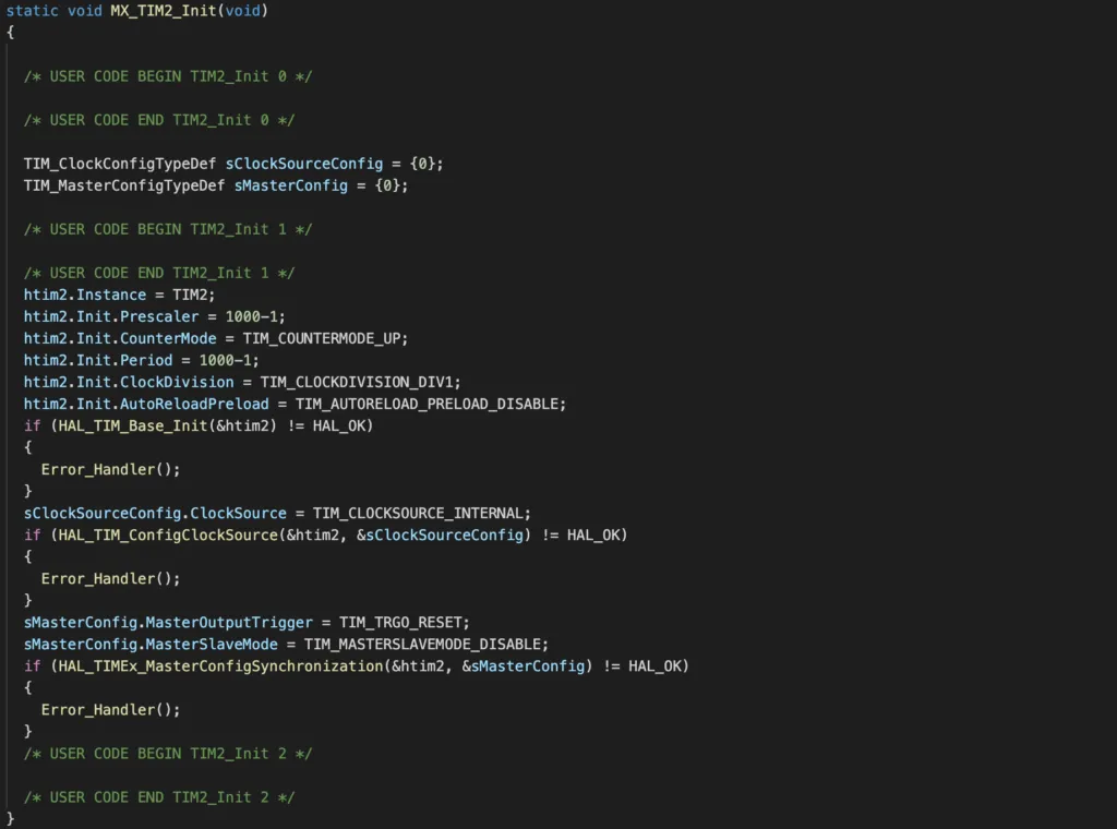
You can also see that the GPIO D10 and USART3 are initialised with MX_GPIO_Init() and MX_USART3_UART_Init(), respectively.
Handling timer 2 interrupt
To handle timer 2 interrupt, we add the following callback function:
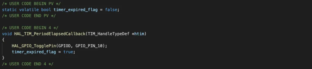
In the callback function, we simply use HAL GPIO function to toggle GPIO D10 and set a flag to true to indicate that interrupt has happened.
Start the timer 2
We need to start the timer 2 by calling HAL_TIM_Base_Start_IT(), otherwise nothing will happen.

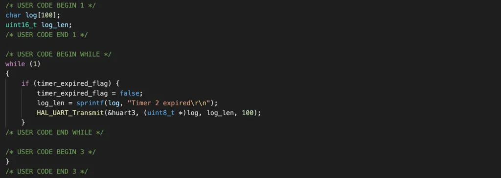
Printing log whenever timer expires
To print log when timer 2 expires, add the following code. It will check if timer 2 flag to see if timer 2 expires. If yes, it will print logs using USART3. It is a good practice to keep interrupt handler as short as possible and handle time-consuming tasks in the main loop. In this project, we toggle a flag in the timer callback and check for the flag in the main loop.
Building, flashing and testing
To build the program, click Project > Build Project. To flash the program, click Run > Run configurations. You’ll need to create a run configuration and select JLink as the debug probe. Then hit Run. Once the program is flashed successfully, you will see the LED on for 1 second, then off for 1 second. Everytime the LED changes its state, a message Timer 2 expired is printed on a UART terminal.
Wrapping Up
In this article, you have learnt the most basic usage of STM32 timers. Compared with other chip families, such as Nordic nRF52, STM32 timers has several capabilities such as external trigger from a pin or PWM generation on an output pin. You’ll need to dig further to STM32 documentation to find out how to do those tasks.