· Stm32 · 6 min read
Using STM32 ADC with STM32CubeIDE and HAL driver
The Analog-to-Digital Converter (ADC) in STM32 microcontrollers is a key feature for reading analog signals in embedded applications. In this blog post, we dive into the essentials of using the STM32 ADC with STM32CubeIDE and the Hardware Abstraction Layer (HAL) driver. We’ll explore the ADC’s features, break down the HAL driver APIs for controlling the ADC, and provide a step-by-step guide to configuring and implementing ADC functionality. Whether you’re measuring sensor data or building precision systems, this tutorial will empower you to leverage the STM32 ADC effectively in your projects.
Introduction
In this post, you will learn about STM32 ADC and how to use it with STM32CubeIDE and HAL driver. We will take a look at STM32 ADC features, then look into APIs of HAL driver using to control the ADC.
To compile and run your code on STM32 hardware, it is recommended that you have a STM32 development kit such as
- STM32 Nucleo-64 Development Board with STM32F303RE MCU
- STM32 Nucleo-64 Development Board with STM32F401RE MCU
- STMicroelectronics NUCLEO-F446RE STM32F446RET6 MCU
Affiliate Disclosure: When you click on links in this section and make a purchase, this may result in this site earning a commission at no extra cost to you.
STM32 ADC Hardware
First, let’s take a look at STM32 ADC hardware and understand it. In this post, we will be using STM32F103VB6. You can find the chip’s datasheet in STM32CubeIDE when creating a new project. Open STM32CubeIDE, select New > STM32 Project. In the Target Selector dialog, type in the Part Number STM32F103VB. Select the variant STM32F103VBTx.
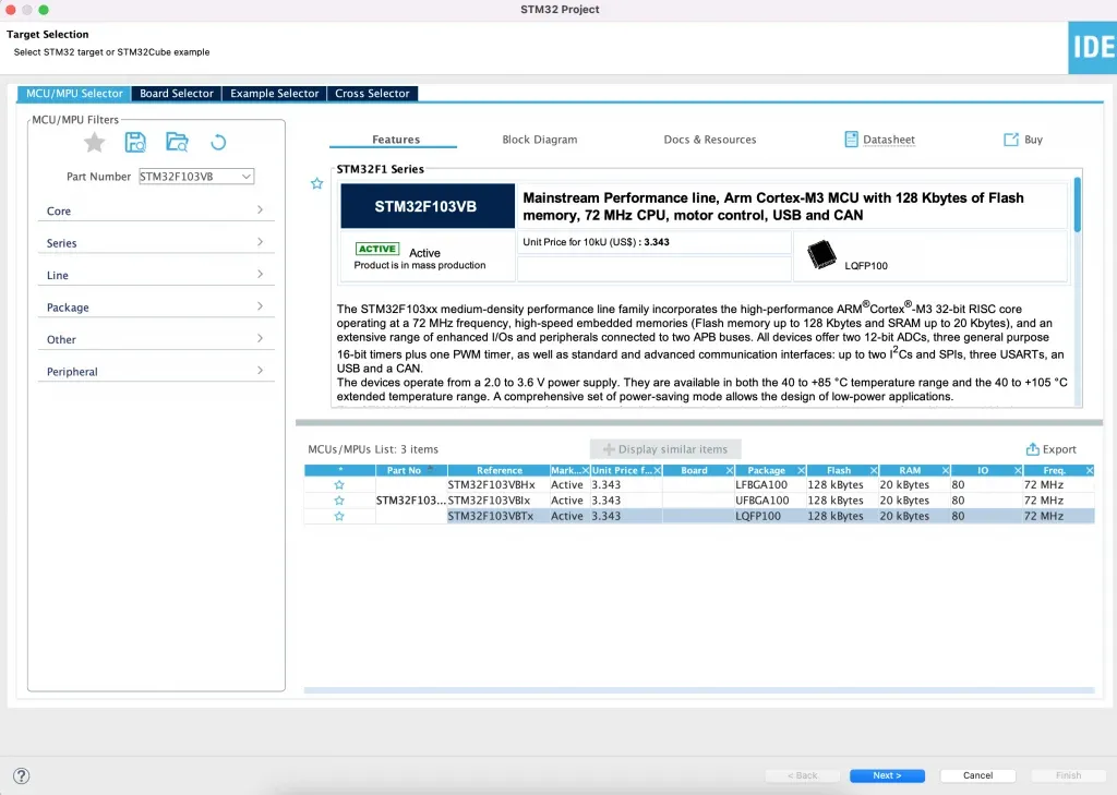
In the Target Selector, you can see a direct link to the chip’s datasheet which is very convenient. If you are using a different STM32 chip, type in your chip model. From the datasheet, you can see the following information about ADC modules that are available on this chip.
- 2x 12-bit, 1us A/D Converters (up to 16 channels)
- Conversion range: 0 to 3.6 V
- Dual sample and hold capacity
- Temperature sensor
ADC instances and pins
The STM32F103VB6 contains 2 ADC hardware blocks, each with 12 bit resolution. Each ADC block shares up to 16 channels. Open Device Configuration Tool in STM32CubeIDE, Select Pinout & Configuration > Analog. You can see there are two ADC blocks named ADC1 and ADC2 that share 16 input pins (IN0 to IN15).
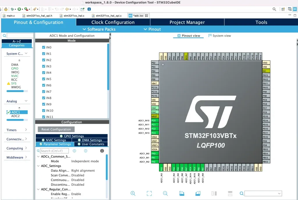
The below table maps ADC pins and I/O pins of STM32F103VB6. When designing your board to use ADC, you will need to pick one of these pre-defined pins to measure analog signals.
| ADC1 Pin | ADC2 Pin | I/O Pin |
|---|---|---|
| ADC1_IN0 | ADC2_IN0 | PA0 |
| ADC1_IN1 | ADC2_IN1 | PA1 |
| ADC1_IN2 | ADC2_IN2 | PA2 |
| ADC1_IN3 | ADC2_IN3 | PA3 |
| ADC1_IN4 | ADC2_IN4 | PA4 |
| ADC1_IN5 | ADC2_IN5 | PA5 |
| ADC1_IN6 | ADC2_IN6 | PA6 |
| ADC1_IN7 | ADC2_IN7 | PA7 |
| ADC1_IN8 | ADC2_IN8 | PB0 |
| ADC1_IN9 | ADC2_IN9 | PB1 |
| ADC1_IN10 | ADC2_IN10 | PC0 |
| ADC1_IN11 | ADC2_IN11 | PC1 |
| ADC1_IN12 | ADC2_IN12 | PC2 |
| ADC1_IN13 | ADC2_IN13 | PC3 |
| ADC1_IN14 | ADC2_IN14 | PC4 |
| ADC1_IN15 | ADC2_IN15 | PC5 |
STM32 ADC operation modes
STM32 ADCs can operate in single shot mode or scan mode.
- In single shot mode, ADC converts analog signal from a single channel (single pin) to digital output.
- In scan mode, you can select a group of channels to be converted.
The ADC can be used with DMA (Direct Memory Access). Using DMA, conversion results can be stored directly to RAM without CPU involvement. We will see how to configure the ADC in different operation modes.
STM32 ADC HAL library
In the previous section, we had a look at the STM32 ADC hardware. In this section, we will examine the APIs in HAL driver to control the ADC. When working with STM32CubeIDE, some of the APIs will be automatically generated and you should understand the meaning of each API. Let’s dive in.
ADC Initialisation
To initialise ADC, use the function HAL_ADC_Init() which has the following prototype and is defined in Drivers/STM32F1xx_HAL_Driver/Inc/stm32f1xx_hal_adc.h
HAL_StatusTypeDef HAL_ADC_Init(ADC_HandleTypeDef* hadc);This function takes a pointer to an ADC instance variable of type ADC_HandleTypeDef and returns an error code of type HAL_StatusTypeDef. If ADC is initialised successfully, HAL_OK is returned. You can declare a variable to store ADC configuration and pass in its address to the initialisation function. You need to specify whether you want to use ADC1 or ADC2 instances. When working with STM32CubeIDE, initialisation is done when you configure the ADC using Device Configuration Tool. STM32CubeIDE generates this code automatically for you
ADC_HandleTypeDef hadc1;

static void MX_ADC1_Init(void)
{
  // Initialising ADC1
  hadc1.Instance = ADC1;
  hadc1.Init.ScanConvMode = ADC_SCAN_DISABLE;
  hadc1.Init.ContinuousConvMode = DISABLE;
  hadc1.Init.DiscontinuousConvMode = DISABLE;
  hadc1.Init.ExternalTrigConv = ADC_SOFTWARE_START;
  hadc1.Init.DataAlign = ADC_DATAALIGN_RIGHT;
  hadc1.Init.NbrOfConversion = 1;
  if (HAL_ADC_Init(&hadc1) != HAL_OK)
  {
    Error_Handler();
  }
  // ...
}
ADC channel initialisation
The next API we look at is ADC channel initialisation function. To initialise an ADC channel, you use the API HAL_ADC_ConfigChannel() defined in stm32f1xx_hal_adc.h
HAL_StatusTypeDef HAL_ADC_ConfigChannel(ADC_HandleTypeDef* hadc, ADC_ChannelConfTypeDef* sConfig);This function takes two arguments: the first argument is a pointer to an ADC handle which you initialised in previous step, the second argument is a pointer to a configuration structure. You can look at the function MX_ADC1_Init() for this snippet
static void MX_ADC1_Init(void)
{
  // ...
  ADC_ChannelConfTypeDef sConfig = {0};
  sConfig.Channel = ADC_CHANNEL_1;
  sConfig.Rank = ADC_REGULAR_RANK_1;
  sConfig.SamplingTime = ADC_SAMPLETIME_1CYCLE_5;
  if (HAL_ADC_ConfigChannel(&hadc1, &sConfig) != HAL_OK)
  {
    Error_Handler();
  }
  // ...
}
Using ADC in blocking mode
In blocking mode, the CPU starts the ADC and wait for ADC to finish conversion. After ADC conversion is finished, it can continue execution. In this mode, CPU is not available to do other things while conversion is happening. To capture ADC data using blocking mode, you use the following APIs
HAL_StatusTypeDef HAL_ADC_Start(ADC_HandleTypeDef* hadc);
HAL_StatusTypeDef HAL_ADC_PollForConversion(ADC_HandleTypeDef* hadc, uint32_t Timeout);
uint32_t HAL_ADC_GetValue(ADC_HandleTypeDef* hadc);
The first function, HAL_ADC_Start() starts the conversion. The second one HAL_ADC_PollForConversion() tells the CPU to wait for the conversion to finish. The last one HAL_ADC_GetValue() is used to retrieve the conversion result. The following example shows how you can get an ADC conversion result in blocking mode.
HAL_ADC_Start(&hadc1);
HAL_ADC_PollForConversion(&hadc1, HAL_MAX_DELAY);
uint32_t adc_value = HAL_ADC_GetValue(&hadc1);
Using ADC in non-blocking mode with interrupt
You can use ADC in non-blocking mode with interrupt. In this mode, you calls the API to start a conversion and specify a callback function which will be executed when the conversion is done. CPU is not blocked and can do other tasks while conversion is happening. To start a conversion in non-blocking mode with interrupt, you use the function HAL_ADC_Start_IT()
HAL_StatusTypeDef HAL_ADC_Start_IT(ADC_HandleTypeDef* hadc);You also need to implement an interrupt service routine which will be called when conversion is finished
void HAL_ADC_IRQHandler(ADC_HandleTypeDef* hadc);
void HAL_ADC_ConvCpltCallback(ADC_HandleTypeDef* hadc);
Using ADC in non-blocking mode with DMA
DMA or direct memory access is a block that allows a peripheral to directly read or write data from memory directly without CPU intervention. You can use ADC in combination with DMA to write conversion results directly to RAM. The API to use ADC with DMA is HAL_ADC_Start_DMA()
HAL_StatusTypeDef HAL_ADC_Start_DMA(ADC_HandleTypeDef* hadc, uint32_t* pData, uint32_t Length);When working with DMA, there are two callbacks which will be called: one when half buffer is filled HAL_ADC_ConvHalfCpltCallback() and the other one is when buffer is fully filled HAL_ADC_ConvCpltCallback()
void HAL_ADC_ConvCpltCallback(ADC_HandleTypeDef* hadc);
void HAL_ADC_ConvHalfCpltCallback(ADC_HandleTypeDef* hadc);
Wrapping Up
In this post, we have looked at the ADC module in STM32 and APIs in HAL driver to work with it. Thanks for reading.