· Stm32 · 9 min read
STM32 SPI Master using STM32CubeIDE and HAL
The Serial Peripheral Interface (SPI) is a powerful communication protocol for connecting STM32 microcontrollers with peripherals like the MAX7219, which drives an 8x8 LED dot matrix. In this blog post, we guide you through creating a project to control a MAX7219-based 8x8 LED matrix using STM32CubeIDE and the HAL library. We’ll cover configuring the STM32 SPI peripheral as a master, exploring HAL APIs for SPI communication, and setting up the MAX7219 to display patterns. With step-by-step instructions, this tutorial helps beginners and experienced developers alike master STM32 SPI for dynamic LED matrix projects.
Introduction
In this article, you will learn how to use STM32 SPI (Serial Peripheral Interface) module. You will build a project to control a 8x8 LED Dot Matrix MAX7219 module using STM32F103. The aim of this post is to help you familiarise with using SPI peripheral in STM32 and steps involved in working with STM32CubeIDE. Let’s get started.
Prerequisites
To follow along with this project, you will need several hardware components which are listed in the below table
| QTY | Component |
|---|---|
| 1 | STM32 development kit |
| 1 | 8x8 LED Dot Matrix MAX7219 |
| 1 | Jumper Wires |
You will need a STM32 development kit, such as a STM32 Nucleo board or any available STM32 boards. In this article, I will use STM32F103VBT6 chip. If you use other chips, in some of the below steps, you might need to do minor modifications, and I will explicitly mention when to make adjustments. Some of development boards have built-in programmer/debugger interface, so you don’t need extra circuitry to program your chip. If your board does not have integrated programmer, you’ll need an external debugger such as SEGGER JLink Lite to flash your program.
For example, you can use the following development kits with built-in programmer
- STM32 Nucleo-64 Development Board with STM32F303RE MCU
- STM32 Nucleo-64 Development Board with STM32F401RE MCU
- STMicroelectronics NUCLEO-F446RE STM32F446RET6 MCU
Affiliate Disclosure: When you click on links in this section and make a purchase, this may result in this site earning a commission at no extra cost to you
8x8 LED Dot Matrix MAX7219 is a popular Arduino-compatible module which has 64 LEDs arranged in 8 rows and 8 columns. If you are not familiar with this module, we have an article describing how to it works which you can reference to. In principle, you control this module by writing to its registers using SPI. You will learn how to use STM32 SPI to write to its register in this post.
You also need STM32CubeIDE installed on your working machine. STM32CubeIDE is an integrated development environment for STM32 chips. You can check out our previous article if you are new to STM32 development.
STM32 SPI peripherals
SPI is a communication protocol between a master device and a slave device which uses 4 pins: CS (Chip Select), CLK (Clock), MOSI (Master In Slave Out) and MISO (Master Out Slave In). Like many other microcontrollers, STM32 chips have dedicated hardware blocks to facilitate SPI transmission, hence eliminate the need to use software to control those tasks. STM32 chips may contain more than 1 instance of SPI peripheral. To check how many SPI instances a chip has, you can refer to its datasheet. Or alternatively, you can use STM32CubeIDE as I will show in a little while. SPI pins are hard-wired to specific IO pins, which is somewhat inflexible compared to other microcontrollers.
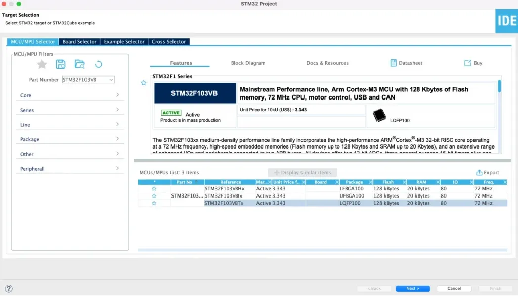
To check SPI instances of STM32, let’s create a new project in STM32CubeIDE by selecting File > New > STM32 Project. Enter the Part Number on the left panel, then select your chip on the right hand side and click Next. From there, you can enter a name for your project and hit Finish.
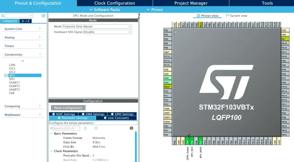
You will now see the Device Configuration Tool screen. Under Connectivity on the left panel, you can see there are two SPI instances SPI1 and SPI2. Clicking on the instance and enabling it, you can see corresponding IO pins are highlighted with green color on the diagram on the right hand side.
The following table describes IO pins associated with SPI1 and SPI2 instances of STM32F103VBT6
| SPI Pins | IO Pins |
|---|---|
| SPI1_SCK | PA5 |
| SPI1_MISO | PA6 |
| SPI1_MOSI | PA7 |
| SPI2_SCK | PB13 |
| SPI_MISO | PB14 |
| SPI_MOSI | PB15 |
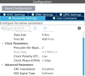
In our project, we will use SPI1 instance. Since we only need to transfer data to MAX7219, MISO pin is not needed. In SPI1 Mode and Configuration, select Mode as Transmit Only Master. In Configuration window, set Parameters as shown in the below figure. This will configure SPI1 to use SPI Mode 0. If you are working with other SPI modules, you may need to change these settings depending on what SPI mode they support.
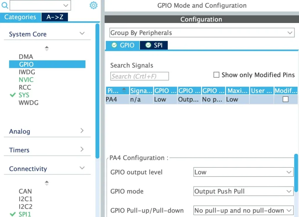
Notice that SPI1 and SPI2 instances do not have CS pins. You can configure any available IO pins as chip select and in your code, you need to manually control CS pin, e.g. to pull it low before sending data and pull it high after data has been transferred. In our project, we will use PA4 as CS pin. Select System Core > GPIO. Configure PA4 as GPIO_Output as shown below
After completing this step, you can close the Device Configuration Tool. When it asks whether to automatically generate code, click Yes. We will take a look at what are generated in the next section.
STM32 SPI HAL APIs
In this section, we will take a look at SPI HAL APIs to initialise and transfer data. Some of initialisation code have been generated automatically based on the configuration that you set in the previous step.
SPI Initialisation
SPI initialisation code is automatically generated based on configuration in Device Configuration Tool. Take a look at main.c, you will see the following function MX_SPI1_Init():
/* Private variables ---------------------------------------------------------*/
SPI_HandleTypeDef hspi1;

// ...

/**
  * @brief SPI1 Initialization Function
  * @param None
  * @retval None
  */
static void MX_SPI1_Init(void)
{

  /* USER CODE BEGIN SPI1_Init 0 */

  /* USER CODE END SPI1_Init 0 */

  /* USER CODE BEGIN SPI1_Init 1 */

  /* USER CODE END SPI1_Init 1 */
  /* SPI1 parameter configuration*/
  hspi1.Instance = SPI1;
  hspi1.Init.Mode = SPI_MODE_MASTER;
  hspi1.Init.Direction = SPI_DIRECTION_2LINES;
  hspi1.Init.DataSize = SPI_DATASIZE_8BIT;
  hspi1.Init.CLKPolarity = SPI_POLARITY_LOW;
  hspi1.Init.CLKPhase = SPI_PHASE_1EDGE;
  hspi1.Init.NSS = SPI_NSS_SOFT;
  hspi1.Init.BaudRatePrescaler = SPI_BAUDRATEPRESCALER_2;
  hspi1.Init.FirstBit = SPI_FIRSTBIT_MSB;
  hspi1.Init.TIMode = SPI_TIMODE_DISABLE;
  hspi1.Init.CRCCalculation = SPI_CRCCALCULATION_DISABLE;
  hspi1.Init.CRCPolynomial = 10;
  if (HAL_SPI_Init(&hspi1) != HAL_OK)
  {
    Error_Handler();
  }
  /* USER CODE BEGIN SPI1_Init 2 */

  /* USER CODE END SPI1_Init 2 */

}
A structure variable hspi1 of type SPI_HandleTypeDef is used to store SPI1’s configuration parameters. The function MX_SPI1_Init() sets the variable hspi1 and calls HAL_SPI_Init() to initialise SPI1 in mode 0.
SPI transfer data API
There are two SPI transfer modes: blocking and non-blocking. Blocking transfer means the CPU will call the transfer function, wait for the transfer to finish and then executes other tasks. During transfer time, CPU is not available to do other jobs. Non-blocking means the CPU calls the transfer function, initiate the transfer and then wait for interrupt indicating transfer has been completed. In this mode, CPU is free to do other tasks and need to handle interrupt routine.
To use blocking transfer, you use API HAL_SPI_Transmit() which accepts a spi handler, pointer to data buffer, data length and a timeout parameter.
HAL_StatusTypeDef HAL_SPI_Transmit(SPI_HandleTypeDef *hspi, uint8_t *pData, uint16_t Size, uint32_t Timeout)To use non-blocking transfer, you use API HAL_SPI_Transmit_IT()
HAL_StatusTypeDef HAL_SPI_Transmit_IT(SPI_HandleTypeDef *hspi, uint8_t *pData, uint16_t Size)These functions are defined in stm32f1xx_hal_spi.h. Note that before calling these functions, you need to manually pull the CS pin low, and after transmission has been completed, you need to pull CS high again. You will see in a little while how to do it with MAX7219.
STM32 SPI MAX7219 code
Now you have understood SPI HAL APIs. Let’s write code to control MAX7219. Add the following code to your main.c file
/* Private define ------------------------------------------------------------*/
/* USER CODE BEGIN PD */
#define DECODE_MODE_REG     0x09
#define INTENSITY_REG       0x0A
#define SCAN_LIMIT_REG      0x0B
#define SHUTDOWN_REG        0x0C
#define DISPLAY_TEST_REG    0x0F
/* USER CODE END PD */

// ...

/* Private user code ---------------------------------------------------------*/
/* USER CODE BEGIN 0 */
static void write_reg(uint8_t reg, uint8_t value) {
  uint8_t tx_data[2] = { reg, value };
  HAL_GPIO_WritePin(GPIOA, GPIO_PIN_4, GPIO_PIN_RESET);
  HAL_SPI_Transmit(&hspi1, tx_data, 2, 100);
  HAL_GPIO_WritePin(GPIOA, GPIO_PIN_4, GPIO_PIN_SET);
}

static void set_row(uint8_t row_index) {
  write_reg(row_index + 1, 0xFF);
}

static void set_col(uint8_t col_index) {
  for (int i = 0; i < 8; i++) {
    write_reg(i + 1, 0x01 << col_index);
  }
}

static void clear(void) {
  for (int i = 0; i < 8; i++) {
    write_reg(i + 1, 0x00);
  }
}

static void max7219_init() {
  write_reg(DISPLAY_TEST_REG, 0);
  write_reg(SCAN_LIMIT_REG, 7);
  write_reg(DECODE_MODE_REG, 0);
  write_reg(SHUTDOWN_REG, 1);
  clear();
}

int main(void) {
// ...
  /* USER CODE BEGIN 2 */
  max7219_init();
  /* USER CODE END 2 */
  /* Infinite loop */
  /* USER CODE BEGIN WHILE */
  while (1)
  {
    /* USER CODE END WHILE */
	for (int i = 0; i < 8; i++) {
	  clear();
	  set_row(i);
	  HAL_Delay(1000);
	}
	for (int i = 0; i < 8; i++) {
	  clear();
	  set_col(i);
	  HAL_Delay(1000);
	}
    /* USER CODE BEGIN 3 */
  }
  /* USER CODE END 3 */
}
Code explanation
- In the above code, you wrote a function write_reg() to transfer data to MAX7219 register using SPI. In this function, you call HAL_GPIO_WritePin() to set chip select pin (PA4) low. Then you call HAL_SPI_Transmit() to transfer SPI data, in this case two bytes of data, one is the register address, the other is the value to write to the register. In this example, you use blocking call. After transfer has been completed, you call HAL_GPIO_WritePin() again to set the chip select pin high.
- You implemented set_row() and set_col() functions to turn all LEDs in a row and all LEDs in a column ON.
- Function clear() is to turn all LEDs off.
- Function max7219_init() is to initialise MAX7219 by setting some default parameters to its registers and turn all LEDs off.
- In the main loop, you implement a simple test which turn each row on, then turn each column on
Testing code
To test the above code, connect STM32 pins and MAX7129 module pins according to this table
| STM32 PIN | 8x8 LED Matrix MAX7219 PIN |
|---|---|
| PA4 | CS |
| PA5 | CLK |
| PA7 | DIN |
| GND | GND |
| VCC | VCC |
To flash and run your program, in STM32CubeIDE, click Run > Run Configuration. Then hit Run to flash your code to target STM32 chip
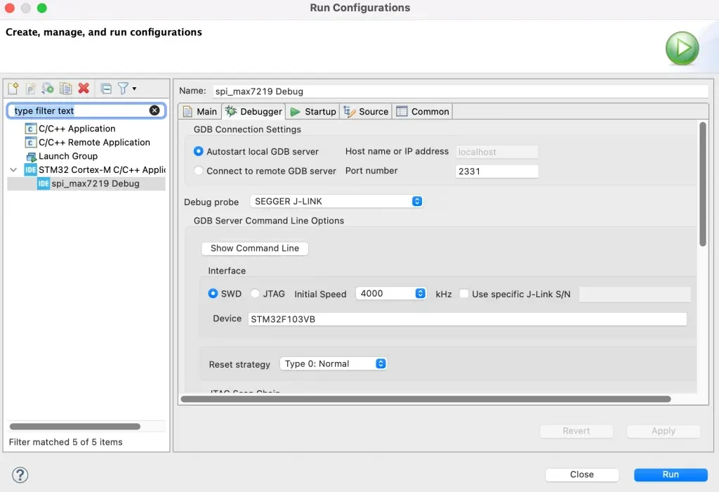
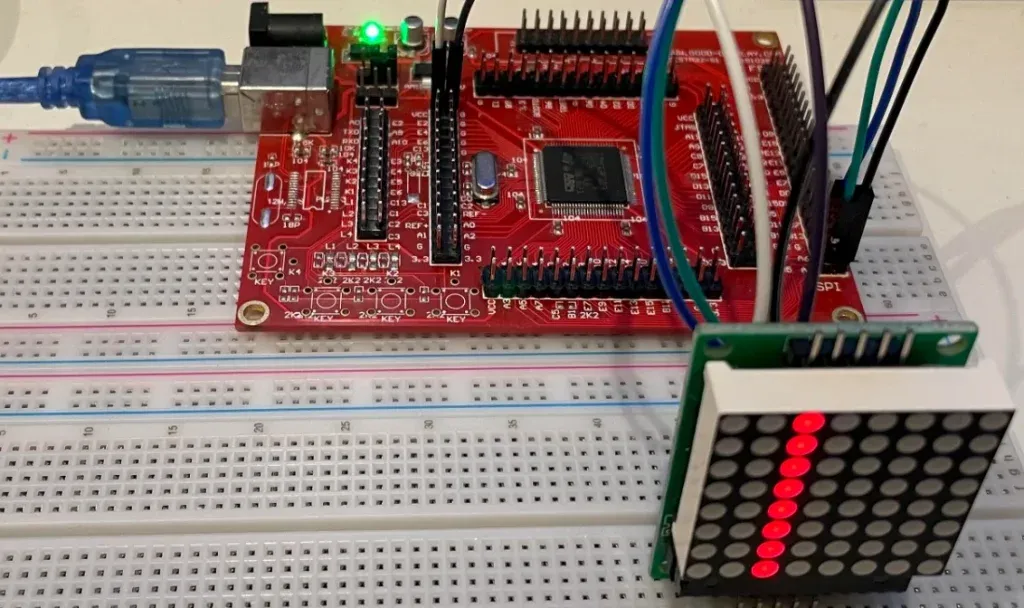
After flashing successfully, you should see each row of the LED Matrix module is turned on and each then each column of the module is turned on, as shown in the below image.
Wrapping Up
In this article, you have learnt how to work with STM32 SPI. You have implemented a project in which SPI is working in Master mode, controlling LEDs in a 8x8 LED Matrix MAX7219.