· Stm32 · 4 min read
Getting started with STM32 Nucleo 64 using STM32CubeIDE
The STM32 Nucleo-64 (L433RC-P) is a powerful and accessible development board for prototyping and developing embedded applications. In this blog post, we’ll guide you through the essentials of getting started with the Nucleo-64 using STM32CubeIDE. From exploring the board’s components and pinouts to setting up the development environment and building a sample project, this tutorial provides a hands-on approach to mastering the STM32 ecosystem. Whether you’re new to STM32 or looking to streamline your workflow, this guide will help you unlock the potential of the Nucleo-64 for your next embedded project.
Introduction
In this post, we will examine the STM32 Nucleo-64 development board L433RC-P, understand its components and pinouts and build a sample project with STM32CubeIDE. This post is a prepration step for exploring future projects with LC33RC-P board.
STM32 Nucleo-64 L433RC-P hardware
There are different variants of STM32 Nucleo-64 boards, for example
- STM32 Nucleo-64 L433RC-P
- STM32 NUCLEO-G491RE
- STM32 NUCLEO-F411RE
- STM32 NUCLEO-G071RB
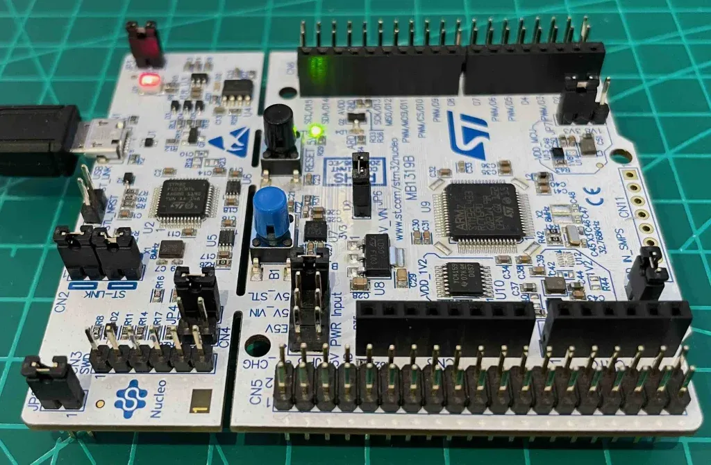
We will take a close look at STM32 Nucleo-64 L433RC-P as shown below
Microcontroller
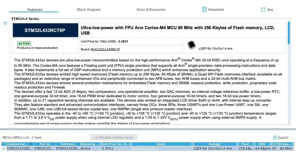
At the heart of the board is the microcontroller STM32L433RCT6P in a 64-pin LQFP package. This microcontroller has the following features:
- Power supply: 1.71 V to 3.6 V
- Core: 32-bit ARM Cortex M4 with FPU
- Clock frequency: Up to 80 MHz
- RAM memory: 64 KB of SRAM
- Flash memory: 256 KB
- IO pins: 50
- Peripherals:
- 1x 12-bit ADC
- 2x 12-bit DACs
- 3x SPIs
- 3x I2C
- 4x USARTs
- and more…
If you are using STM32CubeIDE, you can see these information displayed when you select the target chip, as shown below
Board components
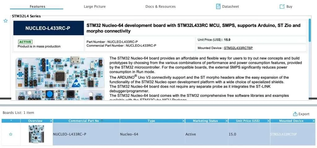
The board STM32 Nucleo-64 L433RC-P includes the chip STM32L433RCT6P and integrates ST Link programmer/debugger so you don’t need external programmer to flash program onto the chip. When installing STM32CubeIDE, you will also install the ST Link driver that is necessary to communicate with the board. STM32CubeIDE makes it easy to see board information in Target Selection dialog. From there, you can also find necessary documentations about the board.
What we are interested in is the block diagram of the board which can be found in its User Manual and is shown in the below image
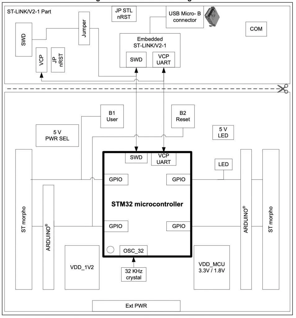
As can be seen from the image, the development board is divided into two sections: one with ST Link interface, the other one contains the microcontroller and circuits to access its pins. The board has 1 user button and 1 reset button, which could be useful to reset the chip to start your program over. There’s 1 user LED which we could use to test a simple blinky program. There are header pins exposed on two sides of the board that allow us to access the microcontroller’s I/Os.
Running your first programs using STM32CubeIDE
Now to test if everything is working properly and the computer can recognise the board, we will build a simple project to test it out. In this project, we will use the LED and button available on the board to do the testing. Notice the following:
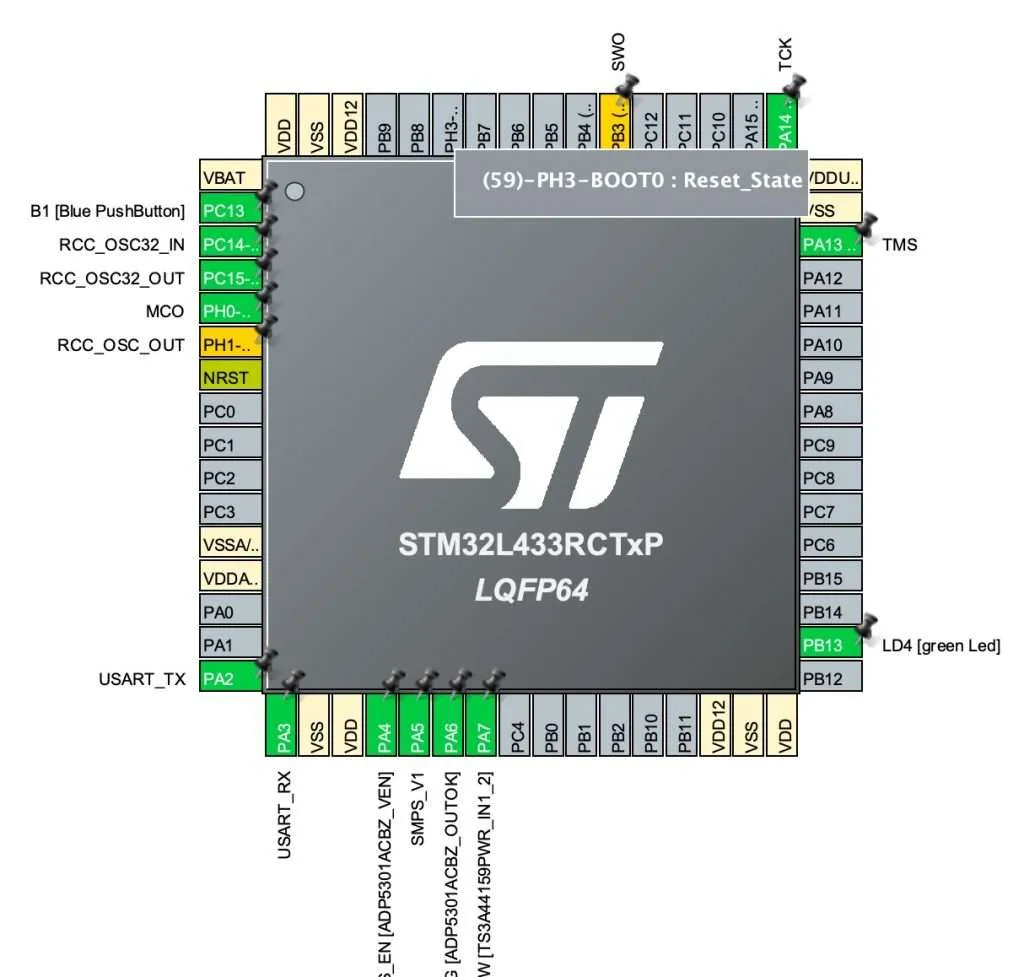
- The LED is connected to I/O pin PB13 and active high, which means writing 1 to PB13 will make the LED turn on and writing 0 to the pin will turn the LED off.
- The button is connected to I/O pin PC13. If button is pressed, we will get 1 when reading the PC13 pin. If button is not pressed, we will read value of 0.
Create new project with STM32CubeIDE
The first step is to create a new project with STM32CubeIDE. In the target selector, you need to choose the target chip STM32L433RCT6P then click Next. Name your project and hit Finish.
Configure I/O pins
Next, open Device Configuration Tool and configure PB13 as output port, PC13 as input port. Click Save and Yes when it asks you to generate code automatically. You can see available I/O pins of the chip graphically which is quite convenient
Adding code
Add the following code to main.c in the main loop. What it does is to check whether the button is pressed and turn on the LED, so that we know it is working properly.
/* USER CODE BEGIN WHILE */
while (1)
{
    if (HAL_GPIO_ReadPin(GPIOC, GPIO_PIN_13) == 1) // button pressed
    {
        HAL_GPIO_WritePin(GPIOB, GPIO_PIN_13, 1);  // turn on led
    } else
    {
        HAL_GPIO_WritePin(GPIOB, GPIO_PIN_13, 0);  // otherwise, turn off led
    }
/* USER CODE END WHILE */
/* USER CODE BEGIN 3 */
}
Build and flash your program
To build your program, click Project > Build Project. It will generate binary file that can be loaded on the STM32.
To flash the program, you will need to create a Run configuration as shown here
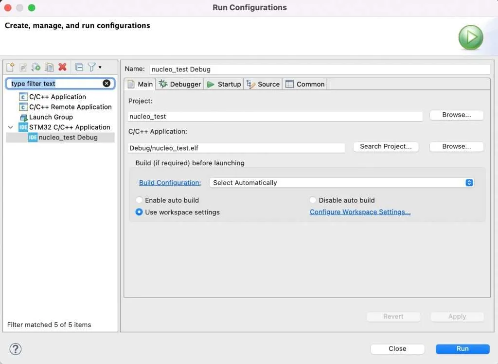
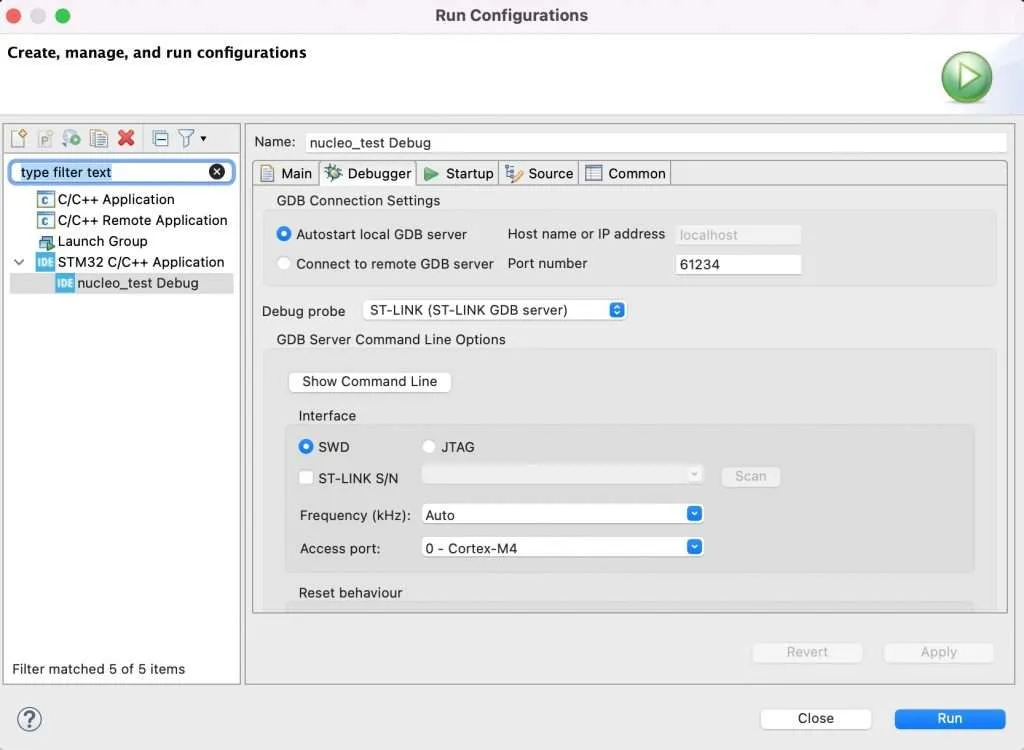
Remember to choose ST-Link as the debugger. Since the board integrates a ST-Link debugger, you don’t need to have extra hardware to make it work.
Click Run to flash your code. You should see your program running as expected.
Note: During flashing your code, it may ask you to update the firmware for ST-Link component of the board. Just follow the prompt and it will work fine after firmware update.
Wrapping Up
In this post, you have learnt how to get started with STM32 Nucleo board L433RC-P. In the next posts, we will explore interesting project built using this development kit. Thanks for reading.